background image

5. Usage 


This product is a device to fix a work-piece when it is processed by the rotary table. 

The handle closes the jaw manually and fixes a work-piece so that it does not move during 

processing. The chuck opens the jaw after having processed it and remove a work-piece. 


22 


・ 

When replacing the top jaw, carefully clean the top jaw and the cross-key (key and 

keyway) of base jaw. If not, it will cause an inadequate deflection accuracy. 


5-1. Precautions during gripping work with chuck


・ 

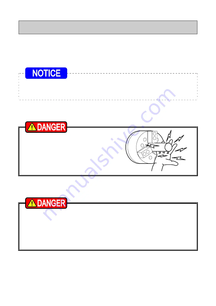
When gripping a work with the 

chuck, do not get fingers or hands 

become caught. This could cause 

crushed or cut fingers and hands. 


5-2. Precautions during gripping work in irregular shape


・ 

If a work in an irregular shape is gripped the jaw may be broken. Consult our 

company or the distributor if there is any concern. 

・ 

Cast metal, pitched shape or taper shape cannot be gripped. 

・ 

If the protrusion of the work is long, support it with a center or the steady rest. 

If the protrusion is long the tip of the work turns, and this is dangerous as the 

work will fly out. 


Summary of Contents for JN N Series

Page 1: ...y Before installing operating or maintaining this equipment carefully read this manual and the safety labels attached to the equipment Failure to follow these instructions and safety precautions could...

Page 2: ...displayed as shown below depending on the damage of risk including the seriousness of the harm that could result Please sufficiently understand the meanings of these terms and follow the instructions...

Page 3: ...any actions unless they are specifically allowed in this manual If any questions related to safety arise about operation control inspection and maintenance which are not specified in this manual pleas...

Page 4: ...ng soft jaw with inside diameter gripping 4 4 Forming method when you use forming jig 5 Usage 22 5 1 Precautions during gripping work with chuck 5 2 Precautions during gripping work in irregular shape...

Page 5: ...hapter 9 9 Attachment 33 9 1 Outline drawing of attachment 9 2 Manufacturing of back plate 9 3 Attachment of chuck 10 Other Information 38 10 1 About standards and orders 10 2 Information about markin...

Page 6: ...1 Structural Drawing and Parts List 1 1 Type display Type display as shown below Fig 1 1 2 Structural drawing Fig 2 5...

Page 7: ...1 3 Parts list Fig 3 6...

Page 8: ...4 Pinion 3 3 3 3 5 Base jaw 3 6 Top jaw 3 7 Soft jaw 3 3 8 Internal jaw 3 3 3 9 External jaw 3 3 3 10 Handle 1 1 1 1 11 Chuck attaching bolt 3 6 3 3 3 12 Jaw attaching bolt 6 13 Cover attaching bolt...

Page 9: ...uck may start rotation suddenly and a part of the body or clothing may be caught For All Users OFF Close door before rotating spindle If the door is not closed you may touch the rotating chuck or the...

Page 10: ...is insufficient or excessive the bolt will break which is dangerous as the chuck or work will fly out Fix the spindle or the chuck when you tighten bolts Your hand could slip and get injury when you w...

Page 11: ...may scatter when you forget to remove it Excessive handle torque can lead to breakage of the chuck this is dangerous as the jaw and work will fly out If the handle torque is insufficient this is dange...

Page 12: ...failure due to lower hydraulic pressure lowers the gripping precision and causes abnormal wearing and seizing etc This is dangerous as the work could fly out from a drop in the gripping force Do not...

Page 13: ...m 3 0 4 5 6 5 Balance quality G6 3 Storing temperature Operating temperature 20 50 10 40 Table 2 2 Type SC 5FN Hard jaw SC 5FN Soft jaw JN06N JN06TN kN 15 0 12 0 31 0 31 0 Maximum static gripping forc...

Page 14: ...kgf m 11 0 11 0 15 0 15 0 Balance quality G6 3 Storing temperature Operating temperature 20 50 10 40 Table 2 4 Type JN10N JN10TN JN12N JN12TN kN 46 0 46 0 55 0 55 0 Maximum static gripping force kgf...

Page 15: ...ia kg m2 0 950 1 725 N m 225 6 245 0 Maximum permissible handle torque kgf m 23 0 25 0 Balance quality G6 3 Storing temperature Operating temperature 20 50 10 40 Reference 1kN 101 97kgf 1MPa 10 197kgf...

Page 16: ...160 55 104 102 150 55 150 JN07N 4 72 70 126 124 180 4 72 56 114 112 170 JN07TN 4 68 66 124 122 180 4 180 62 117 115 170 62 170 JN09N 5 84 82 150 150 220 5 84 62 137 135 210 JN09TN 5 80 78 150 148 220...

Page 17: ...relationship between handle torque and gripping force The gripping force is different depending on the state of grease lubrication grease in use height of the jaw etc The maximum static gripping force...

Page 18: ...t the above permissible protruding range Table 4 If exceeded the above range the engaged part strength between the jaw and scroll becomes insufficient thus scattering the chuck jaw or work and resulti...

Page 19: ...que If the torque is insufficient or excessive the bolt will break which is dangerous as the chuck or work will fly out Table 5 Bolt size Tightening torque M5 8 N m M6 13 N m M8 33 N m M10 73 N m M12...

Page 20: ...chuck periphery 3 Gripping of the plug for forming Clamp the plug in the part of D At this time grip by pressing the plug on the chuck front surface in order for the plug not to be tilted 4 Forming P...

Page 21: ...rming Clamp the plug in the part of D At this time grip by pressing the ring on the chuck front surface in order for the ring not to be tilted 4 Forming Process the gripping part dimension D of the wo...

Page 22: ...to the front soft jaw in order to eliminate the runout In the case of SC FN bore the upper face of soft jaw Set the handle torque for forming rather lower than the torque when the work piece is machin...

Page 23: ...tion accuracy 5 1 Precautions during gripping work with chuck When gripping a work with the chuck do not get fingers or hands become caught This could cause crushed or cut fingers and hands 5 2 Precau...

Page 24: ...check that the top jaw locator work etc and the tool and the tool post etc do not interfere at low rotation and then start processing Do not allow anything to impact the chuck jaw and the work The ch...

Page 25: ...5 5 Attachment of locator and jig In the case of attaching the locator and the jig on the chuck body surface tap or drill a hole in the additional process range specified in Fig 7 Fig 7 24...

Page 26: ...4 28 JN12TN 52 53 5 20 74 28 SC 14N 44 55 0 81 13 SC 16N 50 60 0 86 15 A B Additional process impossible dimension H Processible depth of tapping or drilling a hole The chuck can be modified only in t...

Page 27: ...r lubrication repeat opening and closing the jaw several times without gripping work 2 Grease to use Use the designated grease specified in Table 7 If grease other than the designated grease is used s...

Page 28: ...f lubrication Add grease once every day In the case of high rotation or in the case of using a large amount of water soluble coolant increase the frequency of lubrication according to the usage condit...

Page 29: ...of disassembling At this time pay sufficient attention so as not to make a mistake in the numbers of the body 1 the jaw and the pinion 4 Refer to page 36 about the installation procedure 9 3 Attachme...

Page 30: ...000 strokes once every 2 months or more for cutting cast metal If cutting powder or other substances stagnate inside the chuck it will lead to insufficient stroke and a drop in the gripping force and...

Page 31: ...he cutting force is too large Calculate the cutting force and check that it is suitable for the specification of the chuck The Work slips Insufficient grease lubrication Supply grease from the grease...

Page 32: ...sing the machine Continuous use of a broken product or a defective product may cause a serious accident by the chuck or the work flying out Only experienced and trained personnel should do repairs and...

Page 33: ...05 75 SC 16 0 05 0 05 0 03 0 05 0 05 0 03 Test ring mm SC SA type TC TA type Type Size Dia of Test Round Bar Inner dia Outer dia Inner dia Outer dia SC 3N 85 8 10 15 40 60 SC 4N 110 8 15 20 50 80 SC...

Page 34: ...ufacturers personnel who attach a chuck to a machine Please read following instruction carefully when you attach or detach a chuck to machine and please sufficiently understand and follow the instruct...

Page 35: ...un out of the back plate spigot joint diameter run out must be 0 005 mm or less The precision of the processing of the chuck attachment end surface of the back plate and the spigot joint diameter can...

Page 36: ...45 130 4 5 15 3 M10 JN06TN 170 145 130 4 5 15 3 M10 JN07N 195 170 155 4 5 18 3 M10 JN07TN 195 170 155 4 5 18 3 M10 JN09N 235 208 190 5 5 20 3 M12 JN09TN 235 208 190 5 5 20 3 M12 JN10N 275 248 230 5 5...

Page 37: ...nd the end surface run out of the chuck at 0 02mm T I R or less 36 Always tighten the bolts at the specified torque If the torque is insufficient or excessive the bolt will break which is dangerous as...

Page 38: ...nd from the machine as there is a danger of injury or damage if the chuck drops Chuck size inch Eyebolt 9 10 M10 12 14 M12 16 M16 Remove the eyebolt or the belt without fail after using If the chuck i...

Page 39: ...rders Machinery directive 2006 42 EC Annex I EN ISO 12100 1 2003 A1 2009 EN ISO12100 2 A1 2009 EN ISO14121 1 2007 EN1550 1997 A1 2008 10 2 Information about markings of product Fig 11 10 3 About dispo...

Page 40: ...ton Nua Wattana Bangkok 10110 Thailand TEL 66 2 712 7479 FAX 66 2 712 7481 KITAGAWA IRON WORKS CO LTD Singapore Branch 02 01 One Fullerton 1 Fullerton Road Singapore 049213 TEL 65 6838 4318 FAX 65 640...

Reviews: