Page
8
○
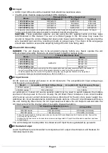
d DC Input
•
All DC Input Wires should be insulated multi-strand low resistance wires.
•
The DC wires must be copper and rated 105
℃
minimum.
Model
Thinnest DC Input Wires Gauge Used
≤ 5 feet (Recommended)
≤ 7.5 feet
≤ 10 feet
12V 2000W series
AWG # 2/0
AWG # 3/0
250 kcmil
12V 3000W series
AWG # 4/0
300 kcmil
400 kcmil
24V 2000W series
AWG # 1/0
AWG # 2/0
AWG # 3/0
24V 3000W series
AWG # 2/0
AWG # 3/0
AWG # 4/0
The typically recommended wire length is limited to 5 feet or less for each of the positive and the negative. For longer
wires, a proportionally thicker gauge is required to compensate for additional voltage drop
CAUTION:
These guidelines assume you are using the DC supplied cable and fuse sizes
recommended in this manual. The use of a thinner gauge in the DC wires may cause the
inverter to trigger the under-voltage shut down under heavy load conditions. It may also melt the
wire insulation and catch fire, resulting in death or serious injury. The choice of the wire gauge
should also match or exceed the ampacity rating of the DC fuse being used.
○
e Chassis DC Grounding
DANGER:
The unit chassis has to be grounded properly before use. Never operate the unit
without proper grounding. Failure to do so will result in death or serious injury.
Model
Thinnest Wire Gauge Used
Recreation Vehicle
Marine
12V 2000W series
AWG # 8
AWG # 1/0
12V 3000W series
AWG # 3/0
24V 2000W series
AWG # 0/0
24V 3000W series
AWG # 1/0
- These guidelines assume you are using the DC supplied cable and fuse sizes recommended in this manual. If
you are using different sizes, refer to the applicable installation code for the DC grounding detail.
- In marine applications, the main AC-DC ground bonding may require galvanic isolators to avoid galvanic
corrosion. Check your local electrical codes (i.e. NEC, UL, ABYC...).
○
f AC Input Source
An AC source is usually grid power or an AC Generator. The acceptable AC Input voltage rage
and frequency are as shown:
Model
Acceptable AC Input Voltage Range
Acceptable AC Input Frequency Range
120VAC series
90 - 140 VAC
30 - 100 Hz
230VAC series
180 - 260 VAC
30 - 100 Hz
An automatic or manual AC source selector switch can be used to switch between the multiple
sources of shore power to the unit. Usually the AC Main Panel includes a main circuit breaker
which serves as over-current protection and as a disconnect for the AC shore power supply line.
Additional AC circuit breakers serve individual circuits and one of the AC circuit breakers will serve
the unit. During By-Pass mode, the AC Input source will serve the AC Output Load and also the
AC Input current for the charger when it is used to charge the battery.
Model
AC Input Circuit Breaker to serve
the unit
AC Input Wire
120VAC series
30A (maximum)
#10 AWG (minimum)
230VAC series
16A (maximum)
#14 AWG (minimum)
- Follow the electrical and/or building code when you choose AC Branch Breaker and AC Input wire Size. Connect the
unit to any AC Input Source
- Smaller size AC Input wire can be used when a lower amperage rated AC Input Circuit Breaker is used from upstream
to feed the unit.
The unit is designed to acceptable non-Sinewave AC Input Source generated by generator.
○
g AC Hardwire Output
An AC Sub-Panel is recommended to incorporate an AC output circuit breaker and breakers for
individual load circuits.


