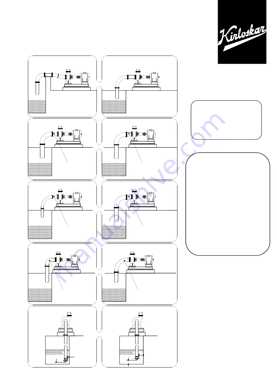
KIRLOSKAR 65-DSM 315M Instruction On Installation, Operation And Maintenance Download Page 73


INCORRECT    CORRECT


D

D

SPACE AROUND

FOOT VALVE

INSUFFICIENT 

SHORT BEND

REDUCED SUCTION PIPE

D

D

SUFFICIENT 

FOOT VALVE

SPACE AROUND

LONG BEND

INCREASED SUCTION PIPE

CONCENTRIC TAPER PIECE

INCORRECT LAYOUT OF SUCTION PIPE

ECCENTRIC TAPER PIECE

CORRECT LAYOUT OF SUCTION PIPE


FOR RECOMMENDATIONS OF 

SUITABLE SUCTION AND 

DELIVERY PIPE SIZE PLEASE 

CONTACT OUR AUTHORISED 

DEALER OR NEAREST 

REGIONAL OFFICE


GENERAL 
INSTRUCTIONS 
FOR 
INSTALLATION 
OPERATION & 
MAINTENANCE OF 

KIRLOSKAR 
CENTRIFUGAL 
PUMPS


®  Registered users – Kirloskar Brothers Ltd. 

Summary of Contents for 65-DSM 315M

Page 1: ...INSTRUCTIONS ON INSTALLATION OPERATION AND MAINTENANCE FOR KIRLOSKAR PUMP TYPE DSM STANDARD KIRLOSKAR BROTHERS LIMITED UDYOG BHAVAN TILAK ROAD PUNE 411 002...

Page 2: ...from the date of commissioning of the equipment or 18 months from the date of despatch from our factory whichever is earlier Our liability in respect of any complaint is limited to replacing part par...

Page 3: ...PERATION 4 TECHNICAL DATA 5 MAINTENANCE 6 OVERHAULING 7 SPARE PARTS LIST AND CROSS SECTIONAL DRAWINGS PLEASE FURNISH COMPLETE NAMEPLATE DETAILS NAME OF THE PARTS PART NOS AND MATERIAL OF CONSTRUCTION...

Page 4: ...ion Maintenance of Kirloskar Centrifugal Pumps which is also printed alongwith this booklet must be followed carefully 2 1 The sealing connection piping to the pump stuffing box must be made after ins...

Page 5: ...defects are noticed Do not start the pump unless the defects are rectified Report immediately to the supplier if it is not possible to rectify the defects 3 4 During stopping the pump 3 4 1 Close the...

Page 6: ...nal sealing can be provided against specific request 4 5 3 Stuffing box packing Champion Style 3316 Graphited Cotton Grease packing is used in the pump as a standard supply However stuffing box packin...

Page 7: ...SM6 30 DSM150 45 50 X 65 65 X 80 65 X 80 80 X 100 100 X 125 100 X 125 100 X 125 125 X 150 150 X 200 150 X 175 6305 6306 6306 6307 6309 21309cc 6315 N310 6305 6306 6306 6307 3309 6413 2 x 7310 BG 100 1...

Page 8: ...re All DSM pumps are similar in construction except some minor changes in the parts The important changes are 6 1 1 Shaft sleeves 310 311 are not provided in DSM 3 and DSM 1E 2E 3ME pumps 6 1 2 Stuffi...

Page 9: ...it in clean dry place for further dismantling 6 2 6 Now start dismantling from driving end side Loosen the coupling nut 332 if provided 6 2 7 Take out flexible coupling pump half 390 with help of a pu...

Page 10: ...320 in the keyways provided on the shaft Fix the impellers on the shaft with interstage ring 204 462 in between them First stage impeller should come towards non driving end 6 4 2 Put the shaft sleeve...

Page 11: ...gently and neatly without disturbing the impellers or packing etc Insert the taper pins so that the two halves of the casings will take their proper seat 6 4 8 Now insert the bolts and nuts for upper...

Page 12: ...ect drive Wear ring Interstage ring Cartridge for bearing DE Cartridge for bearing NDE Ball bearing DE Ball bearing NDE Bearing cover DE Bearing cover NDE Bearing COP Shaft sleeve DE Shaft sleeve non...

Page 13: ...Taper pin with washes nuts for lower and upper half casing Pin for casing ring Pin for st box bush Pin for cartridge Pin for interstage diaphragm Drain plug for casing Plug for Suc Del Pressure gauge...

Page 14: ...oupling pin Nut for coupling pin Washer for coupling pin Interstage diaphragm Gasket for shaft sleeve impeller Gasket for adaptor piece Pipe for sealing Pipe for priming only for DSM 6 DSM 150 45 Sock...

Page 15: ...14 CROSS SECTION ASSEMBLY OF DSM 1E CCW CROSS SECTION ASSEMBLY OF DSM 2E CCW...

Page 16: ...15 CROSS SECTION ASSEMBLY OF DSM 4 RM NOTE ALSO FOR DSM 4 RN DSM 4 RR CCW CROSS SECTION ASSEMBLY OF DSM 5 B CCW DSM 5 B F DSM 5 B MODIFIED...

Page 17: ...16...

Page 18: ...17 CROSS SECTIONAL ASSEMBLY OF DSM 3ME CCW NOTE ALSO FOR DSM 3 3 ME...

Page 19: ...4 Ear defenders should be worn where the specified equipment noise level exceeds locally defined safe levels Safety glasses or goggles should be worn where working with pressurised systems and hazardo...

Page 20: ...ETY INSTRUCTIONS WHILE COMMISSIONING OPERATION Do not touch any moving or rotating parts Guards are provided to prevent access to these parts where they have been removed for maintenance they must be...

Page 21: ...fibrous material as these can be hazardous when the fibrous dust is inhaled Be cautious if other supplier s components have been substituted for genuine KBL parts these may then contain hazardous mat...

Page 22: ...NCENTRIC TAPER PIECE INCORRECT LAYOUT OF SUCTION PIPE ECCENTRIC TAPER PIECE CORRECT LAYOUT OF SUCTION PIPE FOR RECOMMENDATIONS OF SUITABLE SUCTION AND DELIVERY PIPE SIZE PLEASE CONTACT OUR AUTHORISED...

Page 23: ...n the factory alignment Re alignment is necessary after the complete unit has been levelled on the foundation and again after the grout has been set and foundation bolts have been tightened The alignm...

Page 24: ...ight of the pipe lines does not fall on the pump The use of minimum number of the bends and other fittings will minimise the frictional losses SUCTION PIPE The suction pipe should be as short as possi...

Page 25: ...ng on the kind of installation and service involved 1 Liquid level above pump level Pump is set below liquid level of source of supply so that liquid always flows to pump under positive head 2 Priming...

Page 26: ...2 14 15 17 18 19 23 25 26 56 57 58 Pump delivers at reduced capacity 1 2 3 4 5 6 7 8 9 10 11 12 13 14 15 17 18 19 20 21 22 56 57 58 Delivery performance deteriorates 1 3 7 9 10 11 12 13 14 19 20 21 22...

Page 27: ...the sealing liquid inlet 26 Sealing liquid omitted 27 Packing incorrectly fitted 28 Gland tightened too much slanted 29 Packing not suitable for operating conditions 30 Shaft sleeve worn in the regio...

Page 28: ...INSTRUCTION ON INSTALLATION OPERATION AND MAINTAINANCE FOR KIRLOSKAR SPLIT CASE PUMP DSM 100 36 DSM125 40 NON THRU BORE...

Page 29: ...1...

Page 30: ...2...

Page 31: ...d stored in a dry place The coupling should be rotated at least once in a month to prevent pitting of bearing surfaces 2 INSTALLATIONS For location preparing foundation installation alignment piping g...

Page 32: ...up its full speed 3 2 2 Open the valve on delivery side slowly 3 2 3 Open the cock for pressure gauge connection 3 3 During running the pump 3 3 1 The pump is running smoothly 3 3 2 The flow of sealin...

Page 33: ...Please contact supplier if the pump is to be used for higher speeds 4 3 Bearings The shaft is supplied with below bearings 6 2 BEARING DETAILS BEARING No SKF OR EQUIVALENT Sr No PUMP TYPE DE NDE 01 02...

Page 34: ...rease Sealing External sealing can be provided against specific request 4 5 3 Stuffing box packing for gland packed pumps Champion Style 3116 Non asbestos packing is used in the pump as a standard sup...

Page 35: ...7 4 5 7 Technical data chart Position of lantern ring from Impeller side NDE side 2 L 3 for gland packing pumps...

Page 36: ...rating spell the pump will be due for overhaul after about 5000 working hours This work should be done by skilled personnel 6 1 Dismantling Procedure for gland packed pumps 6 1 1 Drain the pump by ope...

Page 37: ...Wipe over the shaft 180 with clean light oil 6 2 3 Place the impeller key 320 into the keyway and interstage ring 204 6 2 4 Check the 1st 2nd stage impeller for correct rotation and slide onto the sha...

Page 38: ...casing 6 2 12 Place gland packing 430 lantern ring 227 in insert as per Cross sectional drawing 6 2 13 Fit the shoulder ring 199 onto shaft Ensure that no foreign particle should enter in bearing ass...

Page 39: ...123 in such a way that impeller should not be damage 6 1 7 Remove all the screws of bearing cartridge 241 253 tightened with casing bearing cover 271 and dismantle the bearing cartridge 6 1 8 Remove t...

Page 40: ...ight oil 6 4 3 Place the impeller key 320 into the keyway and interstage ring 204 6 4 4 Check the 1st 2nd stage impeller for correct rotation and slide onto the shaft from DE and NDE TABLE A STUFFING...

Page 41: ...ighten up with the pump casing 6 4 11 Tighten the bearing cover 271 with bearing cartridge 6 4 12 Apply same procedure to the DE end side 6 4 13 Lift the rotating unit by means of crane Place it in lo...

Page 42: ...20 Rotate the shaft by hand to assure smooth turning and that is free from rubbing or binding 7 CROSS SECTIONAL DRAWINGS 7 2 1 NON THRU BORE TYPE PUMP Gland packing type 7 2 2 THRU NON THRU BORE TYPE...

Page 43: ...15 7 1 2 NON THRU BORE TYPE PUMP Mechanical seal type...

Page 44: ...KEY FOR IMPELLER 1 321 KEY FOR COUPLING 1 323 KEY FOR SLEEVE 1 334 SHAFT SLEEVE NUT 4 336 ROUND LOCK NUT 2 415 LOCK WASHER FOR BEARING 2 441 GREASE NIPPLE FOR BEARING 2 450 VENT VALVE 2 519 GASKET FO...

Page 45: ...1 3 2 Component for Gland packed pumps PART NO DESCRIPTION QTY 229 GLAND 2 224 CLAMPING PLATE FOR SPLIT GLAND 2 227 1 SPLIT LANTEN RING 1 228 STUFFING BOX BUSH 2 310 SHAFT SLEEVE 2 430 GLAND PACKING...

Page 46: ...18...

Page 47: ...19...

Page 48: ...20...

Page 49: ...21...

Page 50: ...22...

Page 51: ...23...

Page 52: ...24...

Page 53: ...25...

Page 54: ...26...

Page 55: ...S ON INSTALLATION OPERATION AND MAINTENANCE FOR KIRLOSKAR MULTISTAGE PUMP TYPE DSM THRU BORE DSM 50 20 DSM 65 20 DSM 50 28 DSM 65 32 A B DSM 80 36 KIRLOSKAR BROTHERS LIMITED UDYOG BHAVAN TILAK ROAD PU...

Page 56: ...from the date of commissioning of the equipment or 18 months from the date of despatch from our factory whichever is earlier Our liability in respect of any complaint is limited to replacing part par...

Page 57: ...ST AND CROSS SECTIONAL DRAWINGS Please furnish complete nameplate details name of the parts part nos And material of construction while ordering spare parts for the pumps CAUTION THIS INSTRUCTION MANU...

Page 58: ...ance trouble shooting etc the instructions given in our publication GENERAL INSTRUCTIONS FOR INSTALLATION OPERATION AND MAINTENANCE OF KIRLOSKAR CENTRIFUGAL PUMPS which is also printed along with this...

Page 59: ...rt the pump unless the defects are rectified Report immediately to the supplier if it is not possible to rectify the defects 3 4 During stopping the pump 3 4 1 Close the valve on delivery side 3 4 2 S...

Page 60: ...reduce the leakage 4 5 2 Stuffing box sealing Lantern ring provided for sealing purpose is used only in first stage stuffing box Normally clear cold self liquid only is used for sealing Grease Sealin...

Page 61: ...9 6306 6306 6307 NON DRIVING END 6307 6408 6306 6306 6307 QTY OF GREASE PER BRG Gms 100 100 100 100 100 ST BOX PACKING SIZE IN MM SIZE x LENGTH 10 SQ x 1660 10 SQ x 2010 10 SQ x 1560 10 SQ x 1560 10 S...

Page 62: ...rocedure 6 1 1 Drain the pump by opening air vent valve 450 6 1 2 Remove all the nuts and bolts 572 581 and locating pin 611 of the upper and lower casing flange 6 1 3 Loosen all the insert joint nuts...

Page 63: ...NDE 6 2 5 Place the distance sleeves 201 onto the shaft DE and NDE and using the impeller nut 300 and lock washer 410 tight against the impeller hub Slide the casing rings 199 onto the impellers 6 2 6...

Page 64: ...2 18 Install casing gasket 519 with a light coat grease on both gasket surfaces Carefully align the inner edge of the gasket with the insert O rings 6 2 19 Lower the casing half upper 122 onto place a...

Page 65: ...Plug for Suc Del Pressure gauge connections Plug for sealing Plug for st box leakage water Gland packing Paper packing between 122 123 O ring for shaft sleeve Grease nipple for lubrication Nylon tube...

Page 66: ...IOM DSMT 0010 01 Issue Date 13 10 2000 Page Page 11 14 Last Revision Date CROSS SECTIONAL ASSEMBLY OF DSM 50 28 PUMP CW THRU BORE TYPE PUMP DSM 65 32A B DRG NO TC 172 90 003 0...

Page 67: ...IOM DSMT 0010 01 Issue Date 13 10 2000 Page Page 12 14 Last Revision Date CROSS SECTIONAL ASSEMBLY OF DSM 80 36 PUMP CW THRU BORE TYPE PUMP DRG NO TC 172 90005 0...

Page 68: ...IOM DSMT 0010 01 Issue Date 13 10 2000 Page Page 13 14 Last Revision Date CROSS SECTIONAL ASSEMBLY OF DSM 50 20 PUMP CW THRU BORE TYPE PUMP DRG NO TC 172 86 024 0...

Page 69: ...IOM DSMT 0010 01 Issue Date 13 10 2000 Page Page 14 14 Last Revision Date CROSS SECTIONAL ASSEMBLY OF DSM 65 20 PUMP CW DRG NO TC 172 86 025 1...

Page 70: ...4 Ear defenders should be worn where the specified equipment noise level exceeds locally defined safe levels Safety glasses or goggles should be worn where working with pressurised systems and hazardo...

Page 71: ...ETY INSTRUCTIONS WHILE COMMISSIONING OPERATION Do not touch any moving or rotating parts Guards are provided to prevent access to these parts where they have been removed for maintenance they must be...

Page 72: ...fibrous material as these can be hazardous when the fibrous dust is inhaled Be cautious if other supplier s components have been substituted for genuine KBL parts these may then contain hazardous mat...

Page 73: ...NCENTRIC TAPER PIECE INCORRECT LAYOUT OF SUCTION PIPE ECCENTRIC TAPER PIECE CORRECT LAYOUT OF SUCTION PIPE FOR RECOMMENDATIONS OF SUITABLE SUCTION AND DELIVERY PIPE SIZE PLEASE CONTACT OUR AUTHORISED...

Page 74: ...n the factory alignment Re alignment is necessary after the complete unit has been levelled on the foundation and again after the grout has been set and foundation bolts have been tightened The alignm...

Page 75: ...ight of the pipe lines does not fall on the pump The use of minimum number of the bends and other fittings will minimise the frictional losses SUCTION PIPE The suction pipe should be as short as possi...

Page 76: ...ng on the kind of installation and service involved 1 Liquid level above pump level Pump is set below liquid level of source of supply so that liquid always flows to pump under positive head 2 Priming...

Page 77: ...2 14 15 17 18 19 23 25 26 56 57 58 Pump delivers at reduced capacity 1 2 3 4 5 6 7 8 9 10 11 12 13 14 15 17 18 19 20 21 22 56 57 58 Delivery performance deteriorates 1 3 7 9 10 11 12 13 14 19 20 21 22...

Page 78: ...the sealing liquid inlet 26 Sealing liquid omitted 27 Packing incorrectly fitted 28 Gland tightened too much slanted 29 Packing not suitable for operating conditions 30 Shaft sleeve worn in the regio...

Page 79: ...INSTRUCTIONS ON INSTALLATION OPERATION AND MAINTENANCE FOR KIRLOSKAR PUMP TYPE DSM THRU BORE DSM 100 36 DSM 125 40 DSM 150 46 KIRLOSKAR BROTHERS LIMITED UDYOG BHAVAN TILAK ROAD PUNE 411 002...

Page 80: ...from the date of commissioning of the equipment or 18 months from the date of despatch from our factory whichever is earlier Our liability in respect of any complaint is limited to replacing part par...

Page 81: ...G 7 SPARE PARTS LIST AND CROSS SECTIONAL DRAWINGS Please furnish complete nameplate details name of the parts part nos And material of construction while ordering spare parts for the pumps CAUTION THI...

Page 82: ...FOR INSTALLATION OPERATION AND MAINTENANCE OF KIRLOSKAR CENTRIFUGAL PUMPS which is also printed alongwith this booklet must be followed carefully 2 1 The sealing connection piping to the pump stuffing...

Page 83: ...to be operated for a long time then drain the casing completely 4 TECHNICAL DATA 4 1 Direction of rotation The standard direction of rotation is clockwise when viewed from driving end The pump suitab...

Page 84: ...elf liquid only is used for sealing Grease Sealing External sealing can be provided against specific request 4 5 3 Stuffing box packing Champion Style 3116 Graphited Cotton Grease packing is used in t...

Page 85: ...UIV DRIVING END 6307 6309 N311 NON DRIVING END 3307 3309 2 x 7310 BG QTY OF GREASE PER BRG Cms 100 100 200 ST BOX PACKING SIZE IN MM SIZE x LENGTH 10 SQ x 2250 12 SQ x 2850 12 SQ x 3200 POSITION OF LA...

Page 86: ...ions for leakage etc 6 OVERHAULING With normal daily operating spell the pump will be due for overhaul after about 5000 working hours This work should be done by skilled personnel 6 1 Dismantling and...

Page 87: ...t gland 229 Remove the stuffing box packing 6 2 12 Remove the stuffing box bush 360 Also take out casing ring 190 6 2 13 Take out the shaft sleeve DE 310 Remove the O ring 522 6 3 Start dismantling fr...

Page 88: ...the shaft This completes the assembly of rotating unit 6 4 4 Now lift the above rotating unit and fit it properly in the lower half casing so that pins 610 1 610 2 take their proper seating 6 4 5 Fit...

Page 89: ...ompletes the re assembly While ordering spares specify nameplate details particularly machine numbers given in enclosed spare parts list Also specify quantity required 7 SPARE PART LIST PART NOS DESCR...

Page 90: ...pin Drain plug for casing Plug for Suc Del Pressure gauge connections Plug for sealing Plug for st box leakage water St box packing Paper packing between 122 123 O ring for shaft sleeve Grease nipple...

Page 91: ...IOM DSMT 001 01 Issue Date 13 10 2000 Page Page 12 12 Last Revision Date Drg No TC 172890060 CROSS SECTION ASSEMBLY OF NEW DSM CW NON THRU BORE PUMP DSM 100 36 DSM 125 40 DSM 150 46...

Page 92: ...4 Ear defenders should be worn where the specified equipment noise level exceeds locally defined safe levels Safety glasses or goggles should be worn where working with pressurised systems and hazardo...

Page 93: ...ETY INSTRUCTIONS WHILE COMMISSIONING OPERATION Do not touch any moving or rotating parts Guards are provided to prevent access to these parts where they have been removed for maintenance they must be...

Page 94: ...fibrous material as these can be hazardous when the fibrous dust is inhaled Be cautious if other supplier s components have been substituted for genuine KBL parts these may then contain hazardous mat...

Page 95: ...NCENTRIC TAPER PIECE INCORRECT LAYOUT OF SUCTION PIPE ECCENTRIC TAPER PIECE CORRECT LAYOUT OF SUCTION PIPE FOR RECOMMENDATIONS OF SUITABLE SUCTION AND DELIVERY PIPE SIZE PLEASE CONTACT OUR AUTHORISED...

Page 96: ...n the factory alignment Re alignment is necessary after the complete unit has been levelled on the foundation and again after the grout has been set and foundation bolts have been tightened The alignm...

Page 97: ...ight of the pipe lines does not fall on the pump The use of minimum number of the bends and other fittings will minimise the frictional losses SUCTION PIPE The suction pipe should be as short as possi...

Page 98: ...ng on the kind of installation and service involved 1 Liquid level above pump level Pump is set below liquid level of source of supply so that liquid always flows to pump under positive head 2 Priming...

Page 99: ...2 14 15 17 18 19 23 25 26 56 57 58 Pump delivers at reduced capacity 1 2 3 4 5 6 7 8 9 10 11 12 13 14 15 17 18 19 20 21 22 56 57 58 Delivery performance deteriorates 1 3 7 9 10 11 12 13 14 19 20 21 22...

Page 100: ...the sealing liquid inlet 26 Sealing liquid omitted 27 Packing incorrectly fitted 28 Gland tightened too much slanted 29 Packing not suitable for operating conditions 30 Shaft sleeve worn in the regio...

Page 101: ...blin kbl co in REGISTERED OFFICE Udyog Bhavan Tilak Road Pune 411002 India Phone 91 20 24440156 Fax 91 24440156 GLOBAL PRESENCE Cambodia Egypt India Lao PDR Senegal South Africa Thailand The Netherlan...

Reviews: