6
DCS
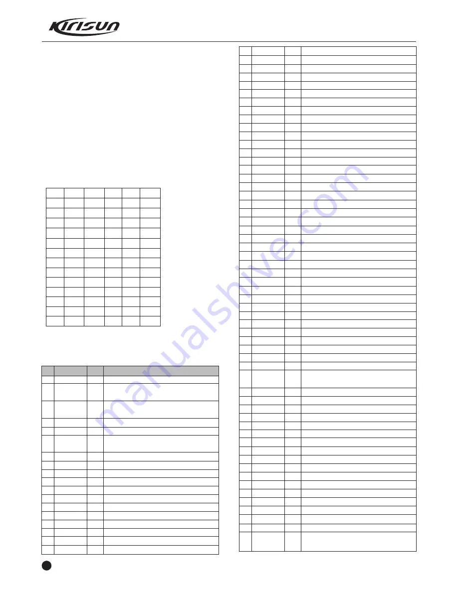
DCS (digital code squelch) is a kind of continuous digital code
modulated with voice signals on carrier wave to control squelch.
83 groups of standard codes (positive and inverse code) are
available. See table 3.2.
DCS signals generated by MCU (PWM wave shape) pass the low
pass filter to be filtered off the high frequency over 300Hz and then
are sent to VCO and TCXO for modulation. VCO modulates the
high frequency of DCS signals; TCXO modulates the low frequency
of DCS signals.
CTCSS/DCS signals from the receiver are sent to MCU for
modulation. MCU determines whether the DCS encoding of the
receiving signals is identical with that set on the radio and decides
whether to turn on the speaker.
Table 3.2 DCS Encoding List
023
114
174
315
445
631
025
115
205
331
464
632
026
116
223
343
465
654
031
125
226
346
466
662
032
131
243
351
503
664
043
132
244
364
506
703
047
134
245
365
516
712
051
143
251
371
532
723
054
152
261
411
546
731
065
155
263
412
565
732
071
156
265
413
606
734
072
162
271
423
612
743
073
165
306
431
624
754
074
172
311
432
627
3.9 Semiconductor Component
MCU Description
Table 3.3 Microprocessor (M30620FCPFP) Port Description
PIN
1
2
3
4
5
6
7
8
9
10
11
12
13
14
15
16
17
18
Port Name
TONEO
APC/TV
AFMUTE
SHIFT
SAVE
BYTE
CNVSS
XCIN
COUT
RESET
XOUT
GND
XIN
VCC
NMI
AFRDF
AFDT
TCLCK
I/O
O
O
O
O
O
I
I
I
O
I
O
I
I
I
I
I
O
I
Function
2T/5T output
,
warning tone output
TX power/ RX sensitivity adjustment
voltage output
RX audio mute control output, H: audio
output; L: mute
Frequency shift selection control
Control Power Save mode output
To select the width of the external data
bus, high level is 8-digit width.
working mode switching control
Backup clock input
Backup clock output
Reset input
Clock output
Ground
Clock input
Power positive polarity input
AK2346 RDF input
AK2346 TATA output
AK2346 MSK clock
19
20
21
22
23
24
25
26
27
28
29
30
31
32
33
34
35
36
37
38
39
40
41
42
43
44
45
46
47
48
49
50
51
52
53
54
55
56
57
58
59
60
61
62
63
64
65
66
67
68
69
70
71
72
73
74
75
CODIO
CTCOUT
PS
NC
NC
NC
NC
CTC_PLL
TONE1
NC
TXD
RXD
CLK1
RTSI
EECLK
EEDAT
NC
NC
NC
NC
NC
NC
NC
NC
NC
WE
NC
NC
NC
NC
NC
EEPROMR/W
NC
W588C
SCLK588
ADA588
BUSY588
NC
T/R
R5C
PLLUS
VCC
T5C
GND
MICMUTE
PLLDAT
PLLCLK
LE
TK
PTT
SK1
SK2
NC
NC
INT
NC
WCON
I/O
O
O
NC
NC
NC
NC
O
I
NC
O
I
I
O
I
O
NC
NC
NC
NC
NC
NC
NC
NC
NC
I
NC
NC
O
O
O
I/O
NC
I
I
O
I
O
O
O
O
I
I
I
I
O
O
I
O
AK2346 DIO input
QT/DQT output
PLL power save mode control
NC
NC
NC
NC
QT/DQT PLL modulation output
2T/5T input test
NC
Serial port output
Serial port input
NC
NC
EEPROM clock wire
EEPROM data wire
NC
NC
NC
NC
NC
NC
NC
NC
NC
MCU read & write control
NC
NC
NC
NC
NC
EEPROM read & write enable
NC
W588 audio chip control
W588 clock
W58 data
W58 test
NC
TX/RX VCO switching control. H
:
RX
,
L
:
TX
R5V voltage control. L
:
R5V output
Unlock check
,
H
:
Lock
,
L
:
Unlock
5V voltage input
T5V voltage control. L
:
T5V output
GND
MIC mute control
。
L
:
mute
PLL data output
PLL clock output
PLL enabling output
Key check
PTT check
Key check
Key check
NC
NC
Low voltage check
NC
Wide band RX control. H:effective in wide
band
PT5200 SERVICE MANUAL


