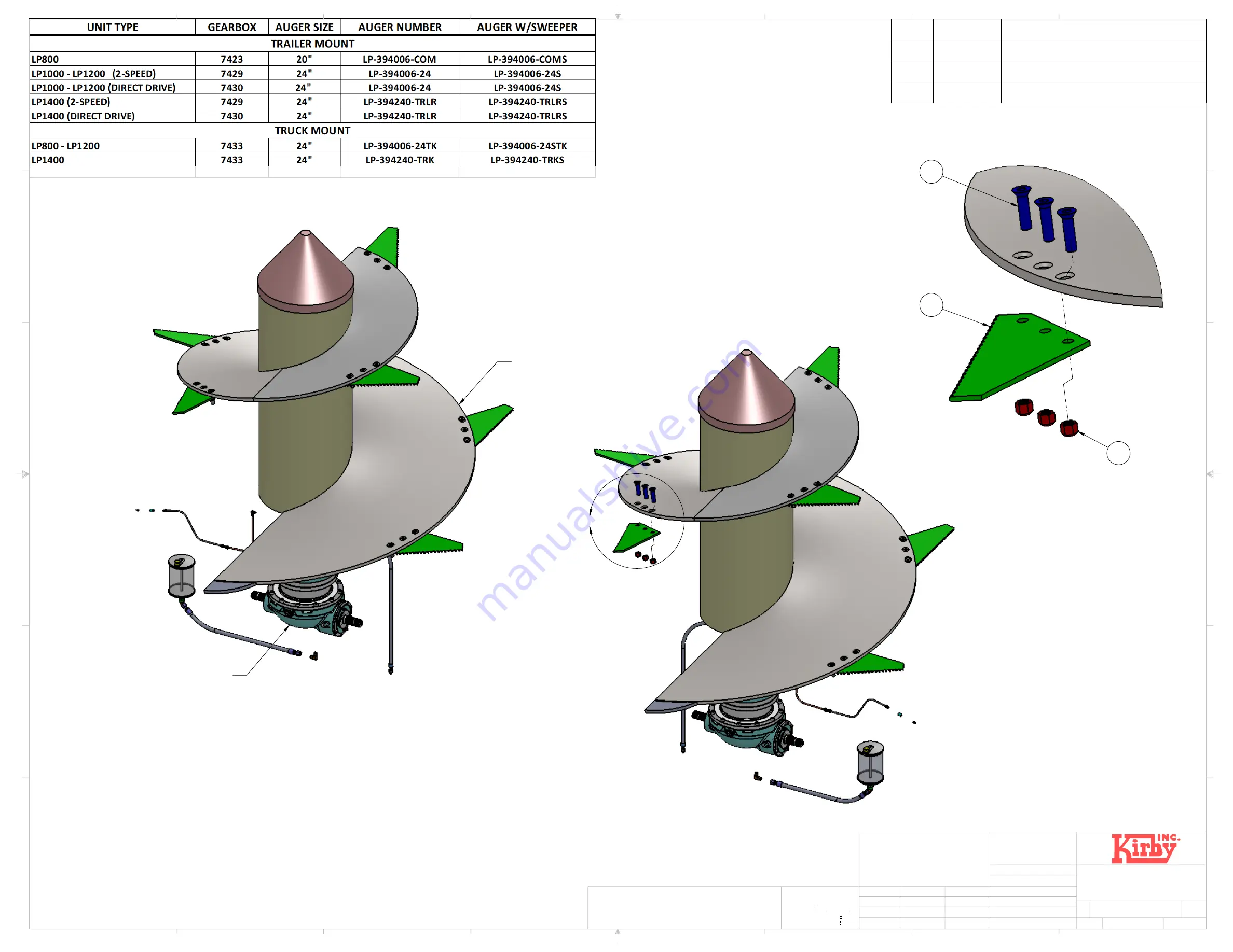
background image

A

AUGER, SEE NOTE-1

GEARBOX, SEE NOTE-1

DETAIL A

3

1

2

NOTE: UNIT SERIAL # NEEDED 

           FOR ALL PART ORDERS

NOTES:


UNLESS OTHERWISE SPECIFIED

1 - SEE TABLE ABOVE FOR AUGER AND GEARBOX SELECTION,

     OTHER VARIATIONS MAY EXIST.

AUGER BLADES SOLD SEPARATELY

ITEM NO. PART NUMBER

DESCRIPTION

1

7774

BLADE, VERTICAL AUGER

2

10647

NUT, 3/4" NC, NYLOCK

3

10730

BOLT, FLTHD SOCKET, 3/4" NC X 3" LG.

D

C

B

A

A

B

C

D

1

2

3

4

5

6

7

8

8

7

6

5

4

3

2

1

E

F

E

F

8-11-17

FINISH:

JOB #:

MATERIAL P/N:

MATERIAL:

SEE BOM

NAME

DATE

APPROVED BY:

DESIGNED BY:

DRAWN BY:

VENDOR:

VENDOR P/N:

SIZE

C

REV.


WEIGHT:

SCALE: 1:12

SHEET 1 OF 1

LP-002D

PART NUMBER

DESCRIPTION

AUGER AND 

GEARBOX SELECTION

MCCLURE

DIMENSIONS ARE IN INCHES

TOLERANCES:

FRACTIONAL

ANGULAR: MACH      BEND 

TWO PLACE DECIMAL    

THREE PLACE DECIMAL  

THE INFORMATION CONTAINED IN THIS DRAWING IS THE SOLE PROPERTY OF

KIRBY MANUFACTURING INCORPORATED.  ANY REPRODUCTION IN PART OR AS

A WHOLE WITHOUT THE WRITTEN PERMISSION OF KIRBY MANUFACTURING

INCORPORATED IS STRICTLY PROHIBITED.

PROPRIETARY AND CONFIDENTIAL

Notes:

P.O. BOX 989

MERCED CA 95340

PH (209)723-0778

FX (209)723-3941

Kirby Mfg Inc.

2790.041763 lbs

8-11-17

Summary of Contents for LP1000

Page 1: ...I Page 1 TRUCK MOUNTED OPERATION AND MAINTENANCE MANUAL TRUCK AND TRAILER MOUNTED V E R T I C A L FEED MIXER Kirby Manufacturing P O Box 989 Merced California 95341 0989 209 723 0778 Kirby Mfg TRAILER MOUNTED ...

Page 2: ...IXER STRUCTURE AND TRAILER 3 0 MAIN AUGERS SHAFTS AND BEARINGS 4 0 SPROCKETS AND CHAINS 5 0 GEARBOXES 6 0 DRIVELINES AND POWER TAKEOFFS 7 0 MAIN HYDRAULIC SYSTEM 8 0 LUBRICATION AND MAINTENANCE 9 0 ELECTRONIC SCALES AND LOADCELLS 10 0 EQUIPMENT OPERATIONS 11 0 SPARE PARTS 12 0 APPENDIX Copyright rev 8 22 2017 ...

Page 3: ...liable for personal injuries or damages loss of time or expense of any kind either direct or indirect resulting from part failure or defect KIRBY MANUFACTURING INC DISCLAIMS ALL OTHER WARRANTIES INCLUDING WITHOUT LIMITATION ANY WARRANTIES EITHER EXPRESSED OR IMPLIED OF MERCHANTABILITY OR FITNESS FOR A PARTICULAR PURPOSE NO AGENT OR EMPLOYEE OF KIRBY MANUFACTURING INC IS AUTHORIZED TO EXTEND ANY OT...

Page 4: ...Truck and all truck parts components truck mounted models i Normal wear and tear for normal replacement parts cutting knives exterior finish chains hydraulic oil filters belts sprockets u joints etc j Scale Systems have their own warranty and are not included in Kirby s limited warranty coverage The warranty stated by the scale manufacturer will be honored by KMI This does not include any freight ...

Page 5: ...Y THEIR TECHNICIAN S WORK TO THE PURCHASER AND MUST INDEMNIFY KMI FROM SUCH CLAIMS DELAYED WARRANTY REPAIRS Warranty repairs should be scheduled and performed as soon as possible after notification of the dealer to KMI There may be extenuating circumstances that require the availability of repair parts necessary to complete the repairs In those cases the dealer must notify KMI in writing of the ex...

Page 6: ...apply to the extended warranty in addition to the special terms and conditions as listed below This policy requires the equipment owner to take and send in oil samples at predetermined time intervals or have an authorized Kirby Service agent maintain and record all service schedules according to owner s manual These time intervals are as follows 1 Gearbox oil samples every 6 months or 1 000 hours ...

Page 7: ...l replace or repair parts and labor 50 of cost replacement and 50 of labor cost Equipment owner s responsibilities to maintain warranty 1 Purchase all sample bottles when purchasing equipment Mechanically driven unit 18 sample kits 6 2 speed 12 planetary Hydraulically driven unit 24 sample kits 12 hydraulic system 12 planetary 4 Perform regular maintenance as specified in the Operation and Mainten...

Page 8: ...g on the mixer unit SAFE OPERATIONS Operation of this mixer feeder shall be limited to competent and experienced persons In addition anyone who will operate or work around a mixer feeder must use good common sense In order to be qualified he or she must also know and meet all other qualifications such as 1 Some regulations specify that no one under the age of sixteen 16 may operate power machinery...

Page 9: ...al word for each has been selected using the following guidelines DANGER Indicates an imminently hazardous situation that if not avoided will result in serious injury or death This signal word is to be limited to the most extreme situations typically for machine components which for functional purposes cannot be guarded WARNING Indicates a potentially hazardous situation that if not avoided will r...

Page 10: ...sense when operating equipment ALWAYS REMEMBER SAFETY FIRST The careful operator is the best operator Most accidents are caused by human error Certain precautions must be observed to prevent the possibility of injury or death DO NOT ALLOW PERSONNEL OTHER THAN THE TRAINED AND QUALIFIED OPERATOR NEAR THE MACHINE NEVER START MACHINE UNTIL ALL GUARDS AND SAFETY SHIELDS ARE IN PLACE DO NOT CLEAN ADJUST...

Page 11: ...ssing Do not attempt to operate this equipment under the influence of drugs or alcohol Review the safety instructions with ALL users annually This equipment is dangerous to children and persons unfamiliar with its operation The operator should be a responsible adult familiar with farm machinery and trained in this equipment s operations Do not allow persons to operate or assemble this unit until t...

Page 12: ... load capacity of the mixer feeder See loading instructions Reduce speed when turning or traveling on rough terrain Avoid traveling over or near loose fill rocks ditches or holes Keep transmissions in gear when traveling downhill KEEP RIDERS OFF MIXER FEEDER Keep riders off Riders are subject to injury such as being struck by foreign objects falling into the mixer and by being thrown off Riders al...

Page 13: ...h Avoid the hazard by relieving pressure before disconnecting hydraulic or other lines Tighten all connections before applying pressure Search for leaks with a piece of cardboard Protect hands and body from high pressure fluids If an accident occurs see a doctor immediately Any fluid injected into the skin must be surgically removed within a few hours or gangrene may result Doctors unfamiliar with...

Page 14: ...or drawbar to recommended setting Disengage power to tractor PTO before turning tractor Remove clevis if equipped Turn offset drawbar down Adjust drawbar length ADJUST TRAILER HITCH CLEVIS Mixer should be approximately level when attached to tractor SAFETY DECAL CARE Keep safety decals and signs clean and legible at all times Replace safety decals and signs that are missing or have become illegibl...

Page 15: ...el speed all times W 300 To prevent serious injury or death Read and understand owner s manual before using Review safety precautions annually No riders allowed when transporting Securely attach to towing unit Use a high strength appropriately sized hitch pin with a mechanical retainer and attach safety chain Do not exceed 20 mph 33kph Slow down for corners and rough terrain Do not drink and drive...

Page 16: ...RRANTY OR MISSING BOLTS REPLACEMENT CHECK MONTHLY FOR LOOSE DAMAGED AUGER BOLTS MUST BE KEPT TIGHT USE ONLY KIRBY AUGER BOLTS FOR 8 MAKE CERTAIN EVERYONE IS CLEAR OF MACHINE BEFORE STARTING ENGINE LUBRICATE CLEAN OR UNCLOG MACHINES UNLESS OTHERWISE SPECIFICALLY 7 USE FLASHING WARNING LIGHTS WHEN OPERATING ON HIGHWAYS EXCEPT 1 KEEP ALL SHIELDS IN PLACE WHEN PROHIBITED BY LAW OBSERVATION IS PROVIDED...

Page 17: ...ible operator If there is any portion of this manual or function you do not understand contact your dealer or Kirby Manufacturing DO NOT WORK ON WITHOUT DISCONNECTING POWER SOURCE KM 07 IF YOU CAN READ THIS THE SHIELD IS NOT IN PLACE SHUT MACHINE OFF REPLACE SHIELD MOVING PARTS FAILURE TO HEED CAN RESULT IN DEATH KM 05 ROTATING AUGER HAVE SPOUT IN UP POSITION WHEN MIXING KEEP HANDS AWAY FAILURE TO...

Page 18: ...Be sure that there are no tools lying on or in the mixer feeder Do not use the unit until you are sure that the area is clear especially of children and animals Always check inside of mixer prior to starting it up Because it is possible that this mixer feeder may be used in dry areas or the presence of combustibles special precautions should be taken to prevent fires and firefighting equipment sho...

Page 19: ...ful when working on inclines Periodically clear the equipment of hay feed twine or other materials to prevent buildup of dry combustible materials Maneuver the tractor or towing vehicle at safe speeds Avoid overhead wires or other obstacles Contact with overhead lines could cause serious injury or death Allow for unit length when making turns Do not walk or work under raised components or attachme...

Page 20: ...governing highway safety and movement of farm machinery on public roads Use approved accessory lighting flags and necessary warning devices to protect operators of other vehicles on the highway during daylight and nighttime transport The use of flashing amber lights is acceptable in most localities However some localities prohibit their use Local laws should be checked for all highway lighting and...

Page 21: ...hut off hydraulic supply and relieve all hydraulic pressure Openings in the skin and minor cuts are susceptible to infection from hydraulic fluid If injured by escaping hydraulic fluid see a doctor at once Gangrene can result Without immediate treatment serious infection and reactions can occur Replace all shields and guards after servicing and before moving After servicing be sure all tools parts...

Page 22: ...and bearings I Check for oil seal leaks Replace if seal leaks II Check wheel hubs for proper bearing tightness Tighten as required III Observe oil level in cap oil must be level with bottom of filler hole Fill with proper lubricant to over flow 3 0 MAIN AUGERS SHAFTS AND BEARINGS CAUTION THE MIXER SHALL NOT BE IN OPERATION FOR THE FOLLOWING 3 1 Observe auger flighting in mixing chamber I Bent defo...

Page 23: ...ckets on shaft Tighten or replace IV Alignment Using a straight bar insure that both sprocket faces are in full contact with the edge of the bar 5 0 GEAR BOXES 5 1 Main planetary drive I Observe oil level of gearbox reservoirs use clear view tube on oil reservoir II Observe for any over fill oil coming out of the gearbox oil reservoir tank 5 2 Two speed gearboxes I Observe shaft seals for leaks Re...

Page 24: ...veline U joints as per the Preventive Maintenance and Lubrication Schedule 6 3 Mixer drive line I Check for loose or missing set screws or lock collars in pillow block bearings and driveline yokes Tighten or replace lock collars set screws II Check for loose or missing bolts in pillow block bearings Tighten or replace III Observe driveline under operation CAUTION STAY CLEAR OF ALL MOVING PARTS DO ...

Page 25: ...replaced if indicated or as hours of use require When replacing the filters always replace O ring on canister Kirby Manufacturing recommends that only authorized Kirby filters be used for replacement The filters used must be at least a 10 micron filter Oil specifications are Pennzoil AW68 It is critical that proper maintenance and filter changes be made on a regular basis Warranty is based on the ...

Page 26: ...eme Pressure additive for other oil choices see the additional specification listed below If you have opted for the Extended Warranty you will be provided with oil sampling kits You should use these kits when pulling oil samples on your equipment It is crucial that oil samples be pulled in accordance to the provided schedule YOUR WARRANTY WILL BE VOID IF ONE OIL SAMPLING TEST IS MISSED Once your o...

Page 27: ...ck mounted models but the system will not come back on until the oil cools down If this failure occurs and you are unable to find the cause call Kirby Mfg Inc 209 723 0778 for further assistance Your system has a hydraulic oil cooling system equipped with fan s which automatically will turn on when the oil temperature reaches 120 degrees The radiator for this system should be cleaned on a daily ba...

Page 28: ... minimum of 46 liters per minute 12 gpm to a maximum of 53 liters per minute 14 gpm to provide adequate unload speed The speed is controlled through the crossfeed flow control valve located on the mixer 7 9 Stalling of the discharge conveyor motor may be caused by the loss of oil pressure P S I to the motor due to incorrect adjustment of relief valve or worn pump motor 7 10 Slow speed of discharge...

Page 29: ... of the discharge III Both have grease zerk that need greasing once a week IV Check that all grease lines and grease zerks are in place and in good working order not plugged loose or kinked V Pump grease using a standard hand pump grease gun 3 to 4 times for each bearing Always be sure the machine is operating and the bearings are rotating to ensure that they take grease Caution Excessive grease w...

Page 30: ...ings X Grease PTO Drive Line Slip Sleeve X Check out Mixer X Repack Wheel bearings X NOTE For a more detailed Preventative Maintenance PM Schedule refer to the Maintenance Schedule Checklist located at the end of this chapter 1 If you have opted for the three 3 year Extended Warranty Policy on all major components it is required that you sample oils on the frequencies stated in the Extended Warran...

Page 31: ...ALSO USE THIS GEAR OIL IN RIGHT ANGLE TEE AND TWO SPEED GEARBOXES 1 Mobil Mobilube SHC 75W 90 2 Chevron Chevron RPM Synthetic Gear Lubricant SAE 75W 90 3 Texaco Texaco Syn Star GL 75W 90 4 Texaco Texaco multigear EP SAE 85W 140 IMPORTANT All gearbox oils MUST have an EP Extreme Pressure additive B PLANETARY GEARBOX TOP BEARING GREASE Use an NLGI Grade 2 grease with an EP Extreme Pressure additive ...

Page 32: ...mpletely fill out information sheet Filling gearbox 1 Fill gearbox via the reservoir hose Note Since gear oil is thick and doesn t flow freely an oil dispensing pump system is needed when re filling oil Dispensing pump pressure should never exceed 10 psi so seals are not damaged 2 IMPORTANT gearbox is full only when oil starts to flow from the high level fill hose do not run mixer until oil is see...

Page 33: ...pling bottle and completely fill out information sheet 7 SECURELY replace plug when last of oil has drained from gearbox C Two Speed Manual Shift Gearbox optional on trailer only Filling gearbox Step 1 Remove fill plug on side of gear box this plug is in the middle of the gearbox 2 Fill gearbox through the fill plug hole Note warm oil will flow quicker 3 Continue filling until oil starts to flow f...

Page 34: ... 5 Tighten the knurled screw 2 So the tube 6 will be fixed to the seal 3 The system is sealed now 6 Screw the open sampling bottle 5 on the VAMPIRE pump 1 7 Carefully clean the sample taking tube to avoid sample contamination 8 Insert the end of the sampling tube through the inlet into the oil The tube should not touch the bottom of the oil tank or oil pan 9 Always hold the sampling bottle in a ve...

Page 35: ...r areas item description check off follow up required y n general 1 are all guards in place notify customer if not 2 start mixer and listen for unusual noises 3 look for worn broken parts 4 lubricate all grease zert fittings and or points of lubrication 5 check drive line shear pin planetary gearbox 1 check oil levels daily fill if needed pull oil sample and change oil every 1000 hrs 1st oil chang...

Page 36: ...e 4 check shift linkage adjustment tighten where applicable 5 check tightness of gearbox mounting bolts PTO 1 check and grease shaft check set screws locking collar 4 WEIGH SYSTEM minor areas item description check off follow up required y n general 1 check operations of scales 2 check for rotation of load ceils 3 check for damaged wiring 4 check and clean load ceil mounting V brackets 5 check loc...

Page 37: ...lters every 500 hrs 5 change hydraulic oil every 4000 hrs approx 1 year 6 check pressure bypass relief settings record 7 check for worn hoses 8 start mixer and listen for unusual noises 9 start mixer and check general operating parameters 10 check driveline to pumps lubricate yokes every 8 hrs a needle lube gun fitting is needed 11 check operations of hydraulic actuators 12 check and record pressu...

Page 38: ...r on chain assembly 2 check for wear on flooring 3 check drive system 4 check conveyor take ups and adjust if needed 5 check operations of cross conveyor slide 4 WEIGH SYSTEM mechanical minor areas item description check off follow up required y n 1 check operations of scales 2 check for rotation of load cells and tighten locking screw 3 check for damaged wiring 4 check and clean load cell mountin...

Page 39: ...s CAUTION DO NOT EXPOSE OPEN WIRES J BOX OR SCALE INSTRUMENTS TO DIRECT FORCE OF WATER All entry points are water resistant but must not be subjected to direct force of water Scale instruments are very dependable but microprocessors are sensitive to electrical interference I For stationary mixer operated from commercial power be sure to confirm that the power source is stable II Check to eliminate...

Page 40: ...rly locked into place on the output PTO of the tractor PTO guard is installed PTO is on and shows no signs of damage Hydraulic lines are installed to the tractor s hydraulic remotes Visual inspect inside of mixer chamber for loose or missing blades clear of any foreign objects If lined with stainless steel liners check for wear Oil levels on planetary gearbox are at the proper levels Visually insp...

Page 41: ...er 540 RPM PTOs Load hay first with mixer running at recommended RPM If after a load you have determined that you hay needs to be cut shorter you may want to check the hay stops and start with pushing in one hay stop for a finer cut If you are not satisfied with the cut length push in the second hay stop and check the RPM of the power source Always remove all twine wire or wrappings from the bales...

Page 42: ...ing to discharge a full load the engine of the tractor should be operating at 1800 RPM and the mixer should be in low gear When 6 000 lbs of mix or less are in your mixer shift two speed gear box on mixer into high speed for a quicker clean out maintain 1800 RPM on tractor s engine TWO SPEED SHIFTING PROCEDURE TRAILER MOUNTS ONLY ALWAYS STOP THE PTO WHEN SHIFTING THE TWO SPEED GEARBOX The shift fe...

Page 43: ...ers turning Once you have discharged the load to a weight that produces less than 3 125psi in the hydraulic circuit the augers will automatically shift back to high speed to assist with a faster clean out If your truck is mixing at a RPM of 1800 rpm your augers will be turning approximately 40 RPM This is with an empty load and minimum pressure needed to turn the augers If you were to load your ha...

Page 44: ...AKE UP COMPONENTS LP 005 CROSSFEED DUAL 36 HYDRAULIC CHAIN LP 006 CHAIN 36 CROSSFEED w FLATBAR LP 007 CRADLE CORSSFEED LP 008A TRAILER TANDEM AXLE LP 008B SUSPENSION TANDEM RUNNING GEAR LP 009A TRAILER SINGLE POINT TANDEM AXLE LP 009B SUSPENSION 900 SERIES SINGLE POINT 50K LP 010A TRAILER SINGLE AXLE LP 010B AXLE ASSEMBLY 10 HOLE ON 11 BC LP 011 TRAILER LP STEERABLE AXLE LP 012 AXLE ASSEMBLY 8 HOL...

Page 45: ... LP 021 COOLER TANK ASSEMBLY LP 022 COOLER MOTOR ASSEMBLY LP 023A SOLENOID MANIFOLD ASSEMBLY TRUCK LP 023B HRDRAULIC SET UP TRAILER LP 024A PUMP MOTOR ASSEMBLY FRONT MOUNT LP 024B PUMP ASSEMBLY FRONT MOUNT LP 025A PUMP MOTOR ASSEMBLY REAR MOUNT LP 025B PUMP ASSEMBLY REAR MOUNT LP 026 FOLDING SPOUT HYDRAULICS LP 027A ELECTRICAL SCHEMATIC VERTICAL TRUCK I LP 027B ELECTRICAL SCHEMATIC VERTICAL TRUCK ...

Page 46: ...D DOOR LH 4 2 391089R SEPARATOR END DOOR RH 5 1 391018 FLOOR LINER 20 AUGER PIPE 6 1 391018 24IN FLOOR LINER 24 AUGER PIPE D C B A A B C D 1 2 3 4 5 6 7 8 8 7 6 5 4 3 2 1 E F E F 8 11 17 FINISH JOB MATERIAL P N MATERIAL SEE BOM NAME DATE APPROVED BY DESIGNED BY DRAWN BY VENDOR VENDOR P N SIZE C REV WEIGHT SCALE 1 24 SHEET 1 OF 1 LP 001 PART NUMBER DESCRIPTION LINERS STAINLESS STEEL MCCLURE DIMENSI...

Page 47: ...50 NUT 5 8 NC 21 26 10592 BOLT 5 8 NC GR8 x 4 LG 22 8 10742 NUT NYLOCK 7 8 NF 23 8 10762 BOLT 7 8 NF GRD 8 x 3 LG 24 2 391211 COMER MOUNTING AND SPACER ASSEMBLY 25 2 13943 6 6 HOSE END 90 3 8 x 3 8 FM JIC SWIVEL 26 2 6 8 FTX S FITTING STR 3 8 MJIC x 1 2 MNPTF 27 2 7429D OIL SEAL COMER FRONT 28 2 7421F OIL SEAL COMER REAR 29 56 10553 WASHER 5 8 LOCK 30 30 7421A BOLT M16 2 0 x 60MM 10 9 COMER 31 2 6...

Page 48: ...ITTING 1 4 M JIC x 1 8 M BSPP 20 2 8 8 CTX S FITTING 90 1 2 M JIC x 1 2 M NPTF 21 2 13943 6 6 HOSE END 90 3 8 x 3 8 FM JIC SWIVEL 22 2 6 8 FTX S FITTING STR 3 8 MJIC x 1 2 MNPTF 23 2 7429D OIL SEAL COMER FRONT 24 2 7421F OIL SEAL COMER REAR 25 2 392029 MOUNTING PLATE ASSEMBLY 26 12 10820A BOLT 1 NC GR8 x 3 LG 27 12 10802 NUT 1 NC NYLON LOCK 28 24 7429C NUT NYLOCK M24 x 3 0 29 24 7429B BOLT SHCS M2...

Page 49: ...LAT 5 8 16 8 10553 WASHER 5 8 LOCK 17 8 10579 BOLT 5 8 NC GR 8 X 2 1 2 18 46 10618 BOLT SHCS 5 8 NC x 8 LG 19 46 10556 NUT NYLOCK 5 8 NC 20 2 8 XHBU S FITTING STRT 1 2 M JIC x 1 2 TUBE 21 2 8 FNTX S END CAP 1 2 FM JIC 22 12 10820A BOLT 1 NC GR8 x 3 LG 23 12 10802 NUT 1 NC NYLON LOCK 24 2 10808 WASHER 1 LOCK 25 2 7433E BOLT HEX M24 x 3 0 x 50 MM LG 26 2 451TC 8 RL HOSE HYDRAULIC 1 2 CUT TO LENGTH D...

Page 50: ...MATERIAL SEE BOM NAME DATE APPROVED BY DESIGNED BY DRAWN BY VENDOR VENDOR P N SIZE C REV WEIGHT SCALE 1 12 SHEET 1 OF 1 LP 002D PART NUMBER DESCRIPTION AUGER AND GEARBOX SELECTION MCCLURE DIMENSIONS ARE IN INCHES TOLERANCES FRACTIONAL ANGULAR MACH BEND TWO PLACE DECIMAL THREE PLACE DECIMAL THE INFORMATION CONTAINED IN THIS DRAWING IS THE SOLE PROPERTY OF KIRBY MANUFACTURING INCORPORATED ANY REPROD...

Page 51: ... x LG 12 4 SEE NOTE 1 DEFLECTOR LIGHT ASSEMBLY 13 2 SEE NOTE 1 TAIL LIGHT ASSEMBLY D C B A A B C D 1 2 3 4 5 6 7 8 8 7 6 5 4 3 2 1 E F E F 8 11 17 FINISH JOB MATERIAL P N MATERIAL SEE BOM NAME DATE APPROVED BY DESIGNED BY DRAWN BY VENDOR VENDOR P N SIZE C REV WEIGHT SCALE 1 50 SHEET 1 OF 1 LP 003A PART NUMBER DESCRIPTION MIXER BODY OPTIONS MCCLURE DIMENSIONS ARE IN INCHES TOLERANCES FRACTIONAL ANG...

Page 52: ...IR PIN 1 8 x 1 3 4 4 1 10578 BOLT 5 8 NC GR5 x 2 1 2 LG 5 1 10556 NUT NYLOCK 5 8 NC ITEM NO QTY PART NUMBER DESCRIPTION 1 1 5317 REMOTE DISPLAY LED RD 4000 2 1 5319 CABLE RD4000 REMOTE 33 FT LG 3 1 5316 VISOR SST W SREWS RD4000 4 4 10110 BOLT 5 16 NC GRD 5 x 1 LG 5 4 10098 WASHER LOCK 5 16 6 4 10090 NUT HEX 5 16 NC 7 4 10099 WASHER FLAT 5 16 D C B A A B C D 1 2 3 4 5 6 7 8 8 7 6 5 4 3 2 1 E F E F ...

Page 53: ...4 1 4690 GROMMET RUBBER 4 RND LIGHT D C B A A B C D 1 2 3 4 5 6 7 8 8 7 6 5 4 3 2 1 E F E F 8 15 17 FINISH JOB MATERIAL P N MATERIAL SEE BOM NAME DATE APPROVED BY DESIGNED BY DRAWN BY VENDOR VENDOR P N SIZE C REV WEIGHT SCALE 3 4 SHEET 1 OF 1 LP 003C PART NUMBER DESCRIPTION MIXER BODY OPTIONS II MCCLURE DIMENSIONS ARE IN INCHES TOLERANCES FRACTIONAL ANGULAR MACH BEND TWO PLACE DECIMAL THREE PLACE ...

Page 54: ...D 22 1 6704 CHAIN 50 2 CON LINK ITEM NO QTY PART NUMBER DESCRIPTION 23 1 6703 CHAIN 50 2 DRIVE 95 FT LG 24 4 7928 CLEVIS PIN CYLINDER 25 1 8245 CYLINDER HYDRAULIC 2 x 18 26 2 27048 SPROCKET FLOOR DRIVE D667X 27 2 27080 SPROCKET 1 1 4 ID D667X 28 8 11215 COTTER PIN 3 16 x 2 1 2 LG 29 9 10181 BOLT 3 8 16 NC GRD 5 x 1 30 9 10178 WASHER 3 8 LOCK 31 5 10170 NUT 3 8 NC 32 8 10412 BOLT CARRIAGE 1 2 NC x ...

Page 55: ... END 90 3 8 x 3 8 FM JIC SWIVEL 14 1 6 JTX S FITTING TEE 3 8 MALE JIC 15 2 6 6 F6X S FITTING STR SWIVEL 3 8 FJIC X 3 8 MNPTF 16 2 7897A CHECK VALVE 3 8 C600S 17 2 6 6 FTX S FITTING STRT 3 8 MNPTF x 3 8 MJIC 18 2 10017 BOLT HEX 1 4 NC x 3 4 19 2 10009 WASHER LOCK 1 4 20 3 451TC 6 RL HOSE HYDRAULIC 3 8 CUT TO LENGTH D C B A A B C D 1 2 3 4 5 6 7 8 8 7 6 5 4 3 2 1 E F E F 9 18 17 FINISH JOB MATERIAL ...

Page 56: ...FT LG ITEM NO QTY PART NUMBER F 21 4 7928 CLEVIS PIN CYLINDER 22 1 391055 DRIVE SHAFT 36 CROSSFEED 23 1 8245 CYLINDER HYDRAULIC 2 x 18 24 8 11215 COTTER PIN 3 16 x 2 1 2 LG 25 10 10398 WASHER LOCK 1 2 26 10 10390 NUT 1 2 NC 27 2 10416 BOLT 1 2 NC GRD 5 x 1 3 4 LG 28 4 10181 BOLT 3 8 16 NC GRD 5 x 1 29 4 10178 WASHER 3 8 LOCK 30 8 10412 BOLT CARRIAGE 1 2 NC x 1 3 4 LG D C B A A B C D 1 2 3 4 5 6 7 ...

Page 57: ...VENDOR VENDOR P N SIZE C REV WEIGHT SCALE 1 4 SHEET 1 OF 1 LP 006 PART NUMBER DESCRIPTION CHAIN 36 CROSSFEED W FLATBAR MCCLURE DIMENSIONS ARE IN INCHES TOLERANCES FRACTIONAL ANGULAR MACH BEND TWO PLACE DECIMAL THREE PLACE DECIMAL THE INFORMATION CONTAINED IN THIS DRAWING IS THE SOLE PROPERTY OF KIRBY MANUFACTURING INCORPORATED ANY REPRODUCTION IN PART OR AS A WHOLE WITHOUT THE WRITTEN PERMISSION O...

Page 58: ...G 3 2 10025 SCREW TORQUE SELF TAP 1 4 NC x 1 1 4 LG 4 2 391051 RAM MNT LOW PROFILE CROSSFEED D C B A A B C D 1 2 3 4 5 6 7 8 8 7 6 5 4 3 2 1 E F E F 8 10 17 FINISH JOB MATERIAL P N MATERIAL SEE BOM NAME DATE APPROVED BY DESIGNED BY DRAWN BY VENDOR VENDOR P N SIZE C REV WEIGHT SCALE 1 10 SHEET 1 OF 1 LP 007 PART NUMBER DESCRIPTION CRADLE CROSSFEED MCCLURE DIMENSIONS ARE IN INCHES TOLERANCES FRACTIO...

Page 59: ...3 8 LOCK 17 1 10181 BOLT 3 8 16 NC GRD 5 x 1 18 1 22041 BATTERY TRAY 19 4 21313 MOUNTING PIPE LOAD CELL UPPER 20 4 10015 SCREW SET 1 4 NC GRD 5 x 1 LG 21 4 21313 2 MOUNTING PIPE LOAD CELL LOWER 22 4 21257 SPACER LOADCELL BRACKET 23 2 SEE NOTE 3 AXLE ASSEMBLY 24 4 10002 NUT NYLOCK 1 4 NC 25 13 5496 STEEL CONDUIT CLAMP 1 2 D C B A A B C D 1 2 3 4 5 6 7 8 8 7 6 5 4 3 2 1 E F E F 8 11 17 FINISH JOB MA...

Page 60: ...10 16 5863D NUT 7 8 NF x 1 156 TALL D C B A A B C D 1 2 3 4 5 6 7 8 8 7 6 5 4 3 2 1 E F E F 8 11 17 FINISH JOB MATERIAL P N MATERIAL SEE BOM NAME DATE APPROVED BY DESIGNED BY DRAWN BY VENDOR VENDOR P N SIZE C REV WEIGHT SCALE 1 7 SHEET 1 OF 1 LP 008B PART NUMBER DESCRIPTION SUSPENSION TANDEM RUNNING GEAR MCCLURE DIMENSIONS ARE IN INCHES TOLERANCES FRACTIONAL ANGULAR MACH BEND TWO PLACE DECIMAL THR...

Page 61: ...LG 16 4 10762 BOLT 7 8 NF GRD 8 x 3 LG 17 4 10742 NUT NYLOCK 7 8 NF 18 1 10178 WASHER 3 8 LOCK 19 1 10181 BOLT 3 8 16 NC GRD 5 x 1 20 4 10015 SCREW SET 1 4 NC GRD 5 x 1 LG 21 1 22041 BATTERY TRAY 22 4 10002 NUT NYLOCK 1 4 NC 23 2 SEE NOTE 3 AXLE ASSEMBLY 24 1 SEE NOTE 2 HITCH ASSEMBLY D C B A A B C D 1 2 3 4 5 6 7 8 8 7 6 5 4 3 2 1 E F E F 8 11 17 FINISH JOB MATERIAL P N MATERIAL SEE BOM NAME DATE...

Page 62: ...D 24 8 10648 NUT 3 4 NC STEEL LOCK NUT D C B A A B C D 1 2 3 4 5 6 7 8 8 7 6 5 4 3 2 1 E F E F 8 11 17 FINISH JOB MATERIAL P N MATERIAL SEE BOM NAME DATE APPROVED BY DESIGNED BY DRAWN BY VENDOR VENDOR P N SIZE C REV WEIGHT SCALE 1 6 SHEET 1 OF 1 LP 009B PART NUMBER DESCRIPTION SUSPENSION 900 SERIES SINGLE POINT 50K MCCLURE DIMENSIONS ARE IN INCHES TOLERANCES FRACTIONAL ANGULAR MACH BEND TWO PLACE ...

Page 63: ...7 1 10173 NUT NYLOCK 3 8 NC 18 2 10179 WASHER 3 8 FLAT 19 8 10698 BOLT 3 4 NC GRD 5 x 5 1 2 LG 20 8 10650 NUT 3 4 NC 21 8 10658 WASHER LOCK 3 4 22 4 10762 BOLT 7 8 NF GRD 8 x 3 LG 23 4 21257 SPACER LOADCELL BRACKET 24 4 10742 NUT NYLOCK 7 8 NF 25 8 10659 WASHER FLAT 3 4 26 1 SEE NOTE 3 AXLE ASSEMBLY 27 4 10002 NUT NYLOCK 1 4 NC D C B A A B C D 1 2 3 4 5 6 7 8 8 7 6 5 4 3 2 1 E F E F 8 11 17 FINISH...

Page 64: ...3 BEARING TAPPERED 3 1 2 ID INNER 13 2 6214 RACE BEARING INNER 10 HOLE HUB 14 10 6070 SPACER NUT RH DUAL WHEEL INNER 15 10 6068 NUT RH DUAL WHEEL OUTER 16 2 6210a SPINDLE NUT INNER 17 2 6210b SPINDLE WASHER 18 2 6210c SPINDLE NUT OUTER 19 2 6210D WASHER TAB LOCK 2 5 8 ID D C B A A B C D 1 2 3 4 5 6 7 8 8 7 6 5 4 3 2 1 E F E F 8 11 17 FINISH JOB MATERIAL P N MATERIAL SEE BOM NAME DATE APPROVED BY D...

Page 65: ... STRIP 4 3 4 LG 18 1 5881 SUSPENSION STEERABLE AXLE 19 8 6472 TIRE WHEEL 275 70R 22 5 x 8 25 20 4 10762 BOLT 7 8 NF GRD 8 x 3 LG 21 4 10742 NUT NYLOCK 7 8 NF 22 1 10178 WASHER 3 8 LOCK 23 1 10181 BOLT 3 8 16 NC GRD 5 x 1 24 4 10002 NUT NYLOCK 1 4 NC 25 4 10015 SCREW SET 1 4 NC GRD 5 x 1 LG D C B A A B C D 1 2 3 4 5 6 7 8 8 7 6 5 4 3 2 1 E F E F 8 11 17 FINISH JOB MATERIAL P N MATERIAL SEE BOM NAME...

Page 66: ...LE 8 75 B C RH 15 10 6070 SPACER NUT RH DUAL WHEEL INNER 16 10 6068 NUT RH DUAL WHEEL OUTER 17 2 6210a SPINDLE NUT INNER 18 2 6210b SPINDLE WASHER 19 2 6210c SPINDLE NUT OUTER 20 2 6210D WASHER TAB LOCK 2 5 8 ID 21 1 6208 HUB 10 HOLE 8 75 B C LH D C B A A B C D 1 2 3 4 5 6 7 8 8 7 6 5 4 3 2 1 E F E F 8 11 17 FINISH JOB MATERIAL P N MATERIAL SEE BOM NAME DATE APPROVED BY DESIGNED BY DRAWN BY VENDOR...

Page 67: ...PART NUMBER DESCRIPTION 1 1 5590B CLEVIS HITCH 2 1 5590A HITCH BASE 3 2 10860 BOLT 1 NC GRD 8 x 7 LG 4 2 10802 NUT 1 NC NYLON LOCK 5 1 5590D BOLT 3 4 NC GRD 8 x 6 LG 6 1 5590E NUT LOCK 750 10UNC HEX GR8 D C B A A B C D 1 2 3 4 5 6 7 8 8 7 6 5 4 3 2 1 E F E F 8 11 17 FINISH JOB MATERIAL P N MATERIAL SEE BOM NAME DATE APPROVED BY DESIGNED BY DRAWN BY VENDOR VENDOR P N SIZE C REV WEIGHT SCALE 1 4 SHE...

Page 68: ... 2 3 4 5 6 7 8 8 7 6 5 4 3 2 1 E F E F 8 11 17 FINISH JOB MATERIAL P N MATERIAL SEE BOM NAME DATE APPROVED BY DESIGNED BY DRAWN BY VENDOR VENDOR P N SIZE C REV WEIGHT SCALE 1 7 SHEET 1 OF 1 LP 014 PART NUMBER DESCRIPTION SUBFRAME TRUCK MOUNT MCCLURE DIMENSIONS ARE IN INCHES TOLERANCES FRACTIONAL ANGULAR MACH BEND TWO PLACE DECIMAL THREE PLACE DECIMAL THE INFORMATION CONTAINED IN THIS DRAWING IS TH...

Page 69: ...TO DRIVELINE 55CV 1 3 8 x 21 SPLINE 48 LG 8 1 4100 58 PTO DRIVELINE 55CV 1 3 8 x 21 SPLINE 58 LG 8 1 4100B PTO DRIVELINE 55CV 1 3 4 x 20 SPLINE 48 LG 8 1 4100B 58 PTO DRIVELINE 55CV 1 3 4 x 20 SPLINE 58 LG 8 1 4100C PTO DRIVELINE 55CV 1 3 8 x 6 SPLINE 48 LG 8 1 4100C 58 PTO DRIVELINE 55CV 1 3 8 x 6 SPLINE 58 LG D C B A A B C D 1 2 3 4 5 6 7 8 8 7 6 5 4 3 2 1 E F E F 8 11 17 FINISH JOB MATERIAL P N...

Page 70: ... 8 9 4 7586D BOLT 16mm 2 0 x 35mm 8 8 10 2 10031 BOLT 1 4 NC GRD 5 x 1 1 2 LG 11 2 10002 NUT NYLOCK 1 4 NC 12 8 10553 WASHER 5 8 LOCK 13 1 10548 WASHER 9 16 LOCK 14 1 7585C BOLT M14 x 2 0 x 25MM LG 15 2 7586G OIL SEAL SHAFT 2 SPEED 16 1 70163921 SWITCH BOX D C B A A B C D 1 2 3 4 5 6 7 8 8 7 6 5 4 3 2 1 E F E F 2 23 17 FINISH JOB MATERIAL P N MATERIAL SEE BOM NAME DATE APPROVED BY DESIGNED BY DRAW...

Page 71: ...B A A B C D 1 2 3 4 5 6 7 8 8 7 6 5 4 3 2 1 E F E F 8 11 17 FINISH JOB MATERIAL P N MATERIAL SEE BOM NAME DATE APPROVED BY DESIGNED BY DRAWN BY VENDOR VENDOR P N SIZE C REV WEIGHT SCALE 1 4 SHEET 1 OF 1 LP 015C PART NUMBER DESCRIPTION GEARBOX 2 SPEED OPTIONS II MCCLURE DIMENSIONS ARE IN INCHES TOLERANCES FRACTIONAL ANGULAR MACH BEND TWO PLACE DECIMAL THREE PLACE DECIMAL THE INFORMATION CONTAINED I...

Page 72: ...00B 58 PTO DRIVELINE 55CV 1 3 4 x 20 SPLINE 58 LG 28 1 4100C PTO DRIVELINE 55CV 1 3 8 x 6 SPLINE 48 LG 28 1 4100C 58 PTO DRIVELINE 55CV 1 3 8 x 6 SPLINE 58 LG ITEM NO QTY PART NUMBER DESCRIPTION 16 2 10009 WASHER LOCK 1 4 17 2 10001 NUT 1 4 NC 18 2 3693 KEY SQ 3 8 x 2 1 2 LG 19 4 10183 SET SCREW 3 8 NC x 3 8 LG 20 4 10178 WASHER 3 8 LOCK 21 2 10010 WASHER FLAT 1 4 22 1 392165 GUARD ASSEMBLY FRONT ...

Page 73: ...SCREW 3 8 NC x 3 8 LG D C B A A B C D 1 2 3 4 5 6 7 8 8 7 6 5 4 3 2 1 E F E F 8 11 17 FINISH JOB MATERIAL P N MATERIAL SEE BOM NAME DATE APPROVED BY DESIGNED BY DRAWN BY VENDOR VENDOR P N SIZE C REV WEIGHT SCALE 1 2 SHEET 1 OF 1 LP 017 PART NUMBER DESCRIPTION DRIVELINE HYDRAULIC TRUCK PUMP MCCLURE DIMENSIONS ARE IN INCHES TOLERANCES FRACTIONAL ANGULAR MACH BEND TWO PLACE DECIMAL THREE PLACE DECIMA...

Page 74: ... P N MATERIAL NAME DATE APPROVED BY DESIGNED BY DRAWN BY VENDOR VENDOR P N SIZE C REV WEIGHT SCALE 1 10 SHEET 1 OF 1 LP 018A PART NUMBER DESCRIPTION LADDER OPTIONS MCCLURE DIMENSIONS ARE IN INCHES TOLERANCES FRACTIONAL ANGULAR MACH BEND TWO PLACE DECIMAL THREE PLACE DECIMAL THE INFORMATION CONTAINED IN THIS DRAWING IS THE SOLE PROPERTY OF KIRBY MANUFACTURING INCORPORATED ANY REPRODUCTION IN PART O...

Page 75: ...CK 5 16 ITEM NO QTY PART NUMBER DESCRIPTION 17 4 10090 NUT HEX 5 16 NC 18 1 9650 AIR LINE HOSE 1 4 NPTF 19 1 9651 AIR NOZZLE 1 4 NPTF 20 1 9652 FITTING AIR LINE HOSE 1 4 NPTF 21 2 10186 BOLT 3 8 NC x 1 1 4 LG 22 2 10191 BOLT 3 8 NC GR5 x 1 1 2 LG 23 1 393023 SCREEN ASSEMBLY 24 1 SEE NOTE 2 COOLER COVER ASSEMBLY D C B A A B C D 1 2 3 4 5 6 7 8 8 7 6 5 4 3 2 1 E F E F 10 4 17 FINISH JOB MATERIAL P N...

Page 76: ...NOTE UNIT SERIAL NEEDED FOR ALL PART ORDERS ...

Page 77: ...NOTE UNIT SERIAL NEEDED FOR ALL PART ORDERS ...

Page 78: ... HP S FITTING PLUG HEX HEAD 1 NPTF 12 5 3_4 HP S FITTING PLUG HEX HEAD 3 4 NPTF 13 2 1_2 HP S FITTING PLUG HEX HEAD 1 2 NPTF 14 1 SEE NOTE 3 TANK LID 12 HYDRAULIC ASSEMBLY 15 1 7961C ADAPTER HYD COVER BAFFLE 16 1 7961D GASKET 12 HYD END COVER 17 1 7961B BOLT HEX 5 8 NC x 1 3 8 LG D C B A A B C D 1 2 3 4 5 6 7 8 8 7 6 5 4 3 2 1 E F E F 8 11 17 FINISH JOB MATERIAL P N MATERIAL SEE BOM NAME DATE APPR...

Page 79: ...M NPTF 15 1 10643 6 6 HOSE END 3 8 x 3 8 FM JIC SWIVEL 16 1 8 8 CTX S FITTING 90 1 2 M JIC x 1 2 M NPTF 17 1 10643 8 8 HOSE END 1 2 FM JIC SWIVEL 18 3 9284 FITTING NIPPLE 1 NPTF 19 1 ATM2542 GAUGE OIL TEMP W SENDER 20 1 392031 MANIFOLD 21 1 393021 COOLER COVER 22 1 393023 SCREEN FRAME w COVER 23 451TC 6 RL HOSE HYDRAULIC 3 8 CUT TO LENGTH 24 451TC 8 RL HOSE HYDRAULIC 1 2 CUT TO LENGTH 25 451TC 12 ...

Page 80: ...43 8 6 HOSE END 3 8 x 1 2 FM JIC 17 1 8048 VALVE 3 4 CED BLOCK 18 1 8049 VALVE RPGC JAN 3 4 1 19 1 8055 VALVE FLOW CONTROL WITHOUT RELIEF 5 8 20 2 12 CTX S FITTING 90 3 4 M JIC x 3 4 M NPTF 21 2 12 FTX S FITTING 3 4 M JIC X 3 4 M NPTF 22 2 12 C5OX S FITTING 90 3 4 M JIC x 3 4 M O RING 23 1 12 F5OX S FITTING 3 4 MJIC x 3 4 M O RING 24 1 12 F6X S FITTING 3 4 FM JIC x 3 4 M NPTF SWIVEL 25 2 8 10 C5OX...

Page 81: ... HOSE END 3 4 x 3 4 FM JIC SWIVEL 19 1 PD361 TEST PORT 3 8 M O RING 20 1 8074 RELIEF VALVE BODY FEC HYD 21 1 7892 RELIEF VALVE 1 2 22 1 1_4 HP S FITTING PLUG HEX HEAD 1 4 NPTF 23 1 PD343 TEST PORT 1 4 NPTF 24 3 10643 8 6 HOSE END 3 8 x 1 2 FM JIC 25 2 8 8 8 RTX S FITTING TEE 1 2 M JIC x 1 2 M JIC x 1 2 M NPTF 26 1 8 8 CTX S FITTING 90 1 2 M JIC x 1 2 M NPTF 27 1 13943 8 6 HOSE END 90 3 8 x 1 2 FM ...

Page 82: ... 8 FM JIC x 3 8 HOSE SWIVEL 17 2 3_4 X 1_2 PTR S FITTING REDUCER 3 4 M NPTF x 1 2 M NPTF 18 2 6 8 FTX S FITTING 3 8 MJIC x 1 2 MNPTF 19 2 13943 8 6 HOSE END 90 3 8 x 1 2 FM JIC SWIVEL 20 6 6 WTX WLN S FITTING UNION W NUT 3 8 MJIC x 3 8 MJIC 21 3 6 6 F6X S FITTING 3 8 FM JIC SWIVEL x 3 8 M NPTF 22 3 7896 NEEDLE VALVE 3 8 NPTF 23 3 6 6 FTX S FITTING 3 8 MNPTF x 3 8 MJIC 24 6 10143 8 6 HOSE END 3 8 x...

Page 83: ... 15 3 12 V5OX S FITTING 45 3 4 M JIC x 3 4 M O RING 16 16 10425A WASHER 1 2 LOCK HI COLLAR 17 16 10425 BOLT SKTHD 1 2 13 x 2 LG 18 16 10298 WASHER LOCK 7 16 ITEM NO QTY PART NUMBER DESCRIPTION 19 16 10325 BOLT 7 16 NC x 2 LG 20 2 7417A O RING GEARBOX ADAPTER 21 8 7433A WASHER M20 LOCK 22 8 7433B BOLT M20 2 5 x 55 MM LG 23 2 16 20 FSOLO FITTING STRT 1 M FLAT FACE x 1 1 4 O RING 24 2 1JC43 16 16 HOS...

Page 84: ...M JIC X 3 4 O RING 15 1 12 16 C5OX S FITTING 90 3 4 M JIC x 1 M O RING 16 1 16 C5OX S FITTING 90 1 M JIC x 1 M O RING 17 2 12 10 C5OX S FITTING 90 3 4 M JIC x 5 8 M O RING 18 2 10406 BOLT 1 2 NC GRD 5 x 1 1 4 LG 19 6 10398 WASHER LOCK 1 2 20 4 10411 BOLT 1 2 NC GRD 5 x 1 1 2 LG D C B A A B C D 1 2 3 4 5 6 7 8 8 7 6 5 4 3 2 1 E F E F 8 11 17 FINISH JOB MATERIAL P N MATERIAL SEE BOM NAME DATE APPROV...

Page 85: ...JIC SWIVEL 15 2 1JC43 16 16 HOSE END 1 FM SEAL LOCK SWIVEL 16 2 1JS77 16 16 HOSE END 1 FM FLAT FACE SWIVEL 17 2 10343 16 16 HOSE END 1 M JIC x 1 CRIMP 18 3 12 V5OX S FITTING 45 3 4 M JIC x 3 4 M O RING 19 2 16 20 FSOLO FITTING 1 M FLAT FACE x 1 1 4 O RING 20 2 7417A O RING GEARBOX ADAPTER 21 8 7433A WASHER M20 LOCK 22 8 7433B BOLT M20 2 5 x 55 MM LG 23 16 10425A WASHER 1 2 LOCK HI COLLAR 24 16 104...

Page 86: ...3 4 M O RING 15 1 12 S5OX S FITTING TEE 3 4 M JIC x 3 4 M JIC X 3 4 O RING 16 1 16 F5OX S FITTING 1 M JIC x 1 M O RING 17 1 12 16 C5OX S FITTING 90 3 4 M JIC x 1 M O RING 18 6 10398 WASHER LOCK 1 2 19 4 10411 BOLT 1 2 NC GRD 5 x 1 1 2 LG 20 2 10406 BOLT 1 2 NC GRD 5 x 1 1 4 LG D C B A A B C D 1 2 3 4 5 6 7 8 8 7 6 5 4 3 2 1 E F E F 8 11 17 FINISH JOB MATERIAL P N MATERIAL SEE BOM NAME DATE APPROVE...

Page 87: ... 8 M JIC x 3 8 M NPTF 13 4 10030 SCREW SOCKET HEAD CAP 1 4 NC GRD 5 x 1 1 2 LG 14 2 10643 12 8 HOSE END 1 2 x 3 4 FM JIC SWIVEL 15 451TC 6 RL HOSE HYDRAULIC 3 8 CUT TO LENGTH 16 451TC 8 RL HOSE HYDRAULIC 1 2 CUT TO LENGTH D C B A A B C D 1 2 3 4 5 6 7 8 8 7 6 5 4 3 2 1 E F E F 8 11 17 FINISH JOB MATERIAL P N MATERIAL SEE BOM NAME DATE APPROVED BY DESIGNED BY DRAWN BY VENDOR VENDOR P N SIZE C REV W...

Page 88: ......

Page 89: ......

Page 90: ......

Page 91: ...22102F ARMREST JOYSTICK BOX 13 1 5485A1 MICRO SWITCH 14 1 676 3000 SWITCH SPDT ON NONE ON 15 1 676 3010 SWITCH SPDT MOM OFF MOM 16 1 676 3025 SWITCH DPDT ON OFF 17 3 70185514 RELAY SOCKET 8 PIN 18 1 70089073 TIMER CYCLE REPEAT 19 2 70089081 TIMER ON DELAY 20 1 226 1034 ND KNOB POTENTIOMETER 21 1 D381N10K ND POTENTIOMETER DUAL 10K OHM D C B A A B C D 1 2 3 4 5 6 7 8 8 7 6 5 4 3 2 1 E F E F 8 11 17 ...

Reviews: