background image

6

-1

PERIODIC SERVICE

6

eVeRY 50 hOURs

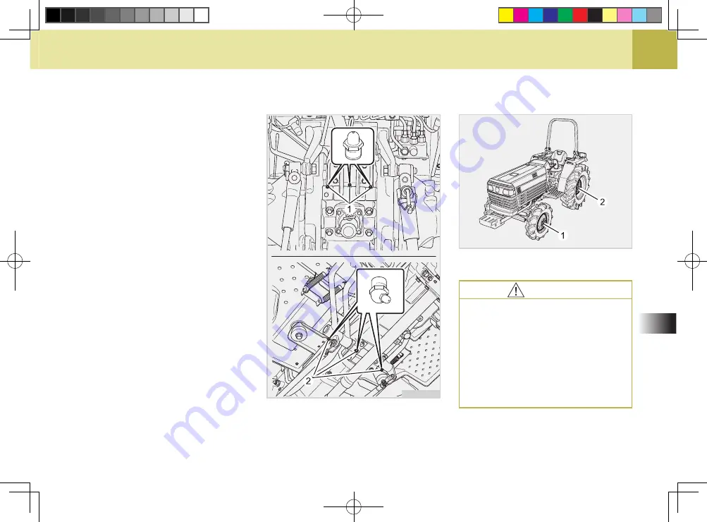
lUBRicatinG GRease FittinGs

You should apply a small amount of 

multi-purpose grease to the following 

points every 50 hours or as needed.
If your tractor is operated in extreme-

ly wet, muddy, or dusty conditions 

you should lubricate the fittings more 

often.

(1) Grease Fittings (Top Link Holder)

(2) Grease Fitting (Brake Pedal,Clutch Pedal)

621Oa17a

Check wheel bolts and nuts regular-

ly especially when new. If they are 

loose, tighten them as follows.

checkinG Wheel BOlt 

tORqUe

(1) 176 N·m (18 kgf·m, 130 lbf·ft)

(2) 284.4 N·m (29 kgf·m, 290.7 lbf·ft)

621Oa18a

caUtiOn

To avoid personal injury:

 

Never  operate  tractor  with  a 

loose rim, wheel, or axle.

 Any  time  bolts  and  nuts  are 

loosened,  retighten  to  speci

-

fied torque.

 

Check  all  bolts  and  nuts  fre

-

quently and keep them tight.

L3503_LK45-호주향-06.indd   17

2008-12-18   오후 1:53:21

Summary of Contents for L3503

Page 1: ...eering Department Knowledge of tractor operation is essential for many years of dependable service and reliability To help new owner s familiarize themselves with the KIOTI L3503 LK45 it is the policy...

Page 2: ...to your vehicle or its equipment if the caution is not heeded Follow the advice provided with the caution This indicates that a condition may result in harm serious in jury or death to you or other pe...

Page 3: ...igh Speed Low Speed HST Hydrostatic Transmission m s Meters Per Second P T O Power Take Off RH LH Right hand and Left hand sides are determined by facing in the direction of forward travel ROPS Roll O...

Page 4: ...itch Differential Lock Low Range Back up light Power Take Off Clutch Con trol On Position Middle Range Turn up light Power Take Off Clutch Con trol Off Position High Range Auto tilling depth work ligh...

Page 5: ...IONS SERVICING OF TRACTOR SPECIFICATIONS DeSCRIPTION OF OPERATING SYSTEM OPERATION PERIODIC SERVICE STORAGE TROUBLE SHOOTING INDEX TABLE OF CONTENTS SECTION 1 9 8 7 6 5 4 3 2 L3503_LK45 00 indd 5 2008...

Page 6: ...L3503_LK45 00 indd 6 2008 12 17 1 55 35...

Page 7: ...RATING THE TRACTOR 1 5 dRIVING THE TRACTOR 1 8 PARKING THE TRACTOR 1 9 OPERATING THE P T O 1 9 USING 3 POINT HITCH 1 10 SERVICING THE TRACTOR 1 10 TRACTOR SAFETY LABELS 1 14 SAFETY PRECAUTIONS 1 1 L35...

Page 8: ...arting the tractor make sure your path is clear of people to avoid accidents caused by sudden movements 8 Before making reverse move ments with your tractor you should always check to see that the pat...

Page 9: ...r unless a passenger seat is installed Keep bystand ers away from the tractor while in operation 14 When getting on and off the trac tor handholds and step plates should always be used This will help...

Page 10: ...en when driving tractors with narrow tread widths For added stability you should adjust your rear wheel tread width see page 5 39 19 Before starting your tractor you should depress the clutch and make...

Page 11: ...injury 2 Do not park your tractor on a steep incline and remember to shut off the engine and P T O before dis mounting the tractor OPERATING THE TRACTOR 3 Do not operate your tractor in an enclosed bu...

Page 12: ...only from the drawbar Nev er hitch anything to the axle hous ing or any other point except the drawbar Pulling from any other lo cation only increase the risk of se rious personal injury or death 6 If...

Page 13: ...operation 15 When working in groups always let the others know what you are going to do before you do it 16 Never freewheel Disengaging the clutch or shifting into neutral while descending a slope as...

Page 14: ...se hazard lights as re quired 1 Lock the brake pedals togeth er when traveling at road speeds Brake both wheels simultaneously when making an emergency stop Uneven braking at road speeds could cause t...

Page 15: ...oad Lock the three point hitch in the raised position 10 When towing other equipment use a safety chain and place an SMV emblem on it as well 1 Disengage the P T O lower all implements place all contr...

Page 16: ...ed implement be sure to install the proper counterbalance weight on the front of the tractor 3 When transporting on the road set the implement lowering control in the LOCK position to hold the im ple...

Page 17: ...6 Do not remove the radiator cap while the coolant is hot When cool slowly rotate the cap to the first stop and allow sufficient time for excess pressure to escape After all the pressure is released r...

Page 18: ...essure has sufficient force to penetrate skin causing serious personal injury Be sure to release all residual pressure Before dis connecting hydraulic lines Before adding pressure to the hy draulic sy...

Page 19: ...lution in mind When replacing cooling water or oil disuse it to the right way Be sure to observe the relevant regulations when you dispose of the engine oil transmission oil fuel coolant filter and ba...

Page 20: ...1 14 L3503 LK45 621O131a TRACTOR SAFETY LABELS L3503_LK45 01 indd 14 2008 12 18 1 51 54...

Page 21: ...1 15 SAFETY PRECAUTIONS 1 1 Part No T2325 50743 4 Part No T2625 55111 2 Part No T2325 50512 3 Part No T2445 50724 5 Part No T2241 50702 6 Part No T2615 54112 L3503_LK45 01 indd 15 2008 12 18 1 51 55...

Page 22: ...1 16 L3503 LK45 7 Part No T2615 53561 8 Part No T2325 50701 L3503_LK45 01 indd 16 2008 12 18 1 51 56...

Page 23: ...SERVICING 2 2 SERVICING OF TRACTOR 2 2 L3503_LK45 02 indd 1 2008 12 18 1 52 04...

Page 24: ...eed of parts be prepared to give your dealer both the tractor and engine serial numbers The tractor serial number is located on the front axle support on the left side of the tractor The engine serial...

Page 25: ...General specifications 3 2 TRAVELING SPEED 3 6 IMPLEMENT LIMITATIONS 3 7 SPECIFICATIONS 3 3 L3503_LK45 03 indd 1 2008 12 18 1 52 14...

Page 26: ...weight ITEM MODEL ITEM MODEL L3503 LK45 L3503 LK45 1 Overall length A1 3 510 138 2 5 Wheel base D 1 780 70 1 1 792 70 6 2 Overall length A2 3 153 124 1 6 Front wheel tread E 1 130 44 5 1 165 45 9 3 O...

Page 27: ...KW HP 26 1 35 33 56 45 PTO Power KW HP 21 15 28 3 28 2 37 8 Rated revolution rpm 2 800 2 600 Capacities Fuel tank L u s gal 42 11 1 Transmission oil L u s gal 28 7 40 26 6 87 Front axle oil L u s gal...

Page 28: ...Brake Wet disc type Differential lock Standard for rear axle Tires Agricultural Front 8 16 4PR 9 5 16 6PR Rear 13 6 24 6PR 13 6 26 6PR Industrial Front Rear Turf Front Rear Hydraulic system Pump capa...

Page 29: ...1 286 2 800 578 2 600 725 2 600 Mid optional PTO shaft Speed PTO rpm engine rpm Min turning radius with one rear wheel braked m feet 2 65 8 69 2 95 9 51 Weight with CABIN kg lbs 1 680 3 704 1 580 3 48...

Page 30: ...1 21 1 75 1 09 2 2 52 1 57 2 27 1 41 2 44 1 52 2 2 1 37 3 3 47 2 16 3 13 1 94 3 36 2 09 3 03 1 88 4 6 21 3 86 5 60 3 48 6 02 3 74 5 42 3 37 High 1 7 78 4 83 7 01 4 36 7 54 4 69 6 8 4 23 2 9 77 6 07 8...

Page 31: ...injury to the operator or others Any malfunctions or failures of the tractor resulting from use with improper implements are not covered by the warranty NOTE Implement size may vary depending on soil...

Page 32: ...MEMO MEMO L3503_LK45 03 indd 8 2008 12 18 1 52 17...

Page 33: ...exterior view 4 2 Instrument Panel and Switches 4 4 Foot and Hand Controls 4 5 DeSCRIPTION OF OPERATING SYSTEM 4 4 L3503_LK45 04 indd 1 2008 12 18 1 52 23...

Page 34: ...4 L3503 LK45 exterior view 621O401a 1 Bonnet RH 2 Head Light 3 Steering Wheel 4 Seat 5 Fuel Inlet Cover 6 Cover ROPS mODEL L3503_LK45 04 indd 2 2008 12 18 1 52 23...

Page 35: ...ION OF OPERATING SYSTEM 4 621O402a 1 Working Lamp 2 Turn Signal Lamp 3 Brake Lamp 4 Top Link 5 PTO Shield Cover 6 Lifting Rod 7 Ass y Check Chain 8 Lower Link 9 Draw Bar L3503_LK45 04 indd 3 2008 12 1...

Page 36: ...itches 1 Fuel Gauge 2 Engine Revolution Gauge 3 Cooling Water Temp Gauge 4 Turn Signal Switch 5 Head Light Switch 6 Horn Switch 7 Engine Emergency Switch 8 Hazard Lamp Switch 9 Key Switch 621O405a L35...

Page 37: ...r 3 Front Wheel Drive Lever 4 Clutch Pedal 5 Brake Pedal Lock 6 Brake Pedal L 7 Brake Pedal R 8 Parking Brake Lock Lever 9 Hi Lo Shift Lever 10 Hand Throttle 11 Foot Throttle 12 Position Control Lever...

Page 38: ...MEMO MEMO L3503_LK45 04 indd 6 2008 12 18 1 52 25...

Page 39: ...PERATING THE TRACTOR 5 11 CHECK DURING DRIVING 5 19 THREE POINT HITCH DRAWBAR 5 28 3 POINT HITCH 5 29 DRAWBAR 5 31 3 POINT HITCH CONTROL SYSTEM 5 31 auxiliary hydraulics 5 34 TIRES 5 38 tread 5 39 BAL...

Page 40: ...ed and maintained determines the life of the tractor A new tractor just off the factory pro duction line has of course been test ed but the various parts are not ac customed to each other therefore ca...

Page 41: ...to new tractors lubrication oil New parts are not accustomed to each other and are not broken in properly Small metal grit can develop in the lubricating system as metal parts be gin to break in and c...

Page 42: ...A IMPORTANT Using starting fluid or ether to start your tractor will cause damage and void your tractors warranty A good way to start your trac tors engine after a long stor age period you should pull...

Page 43: ...Main Gear Shift Lever Hi Lo Gear Shift Lever The main gear shift lever pattern is in the form of an H The hi lo gear shift lever moves two stages high and low By combination and use of the main gear s...

Page 44: ...Control Lever A DOWN 1 Hand Throttle Lever INCREASE DECREASE 1 Clutch Pedal 7 Depress the clutch pedal 8 Turn the key to START po sition and release when the engine starts 621O506A 621O505A 621O504A...

Page 45: ...the en gine is runned If the key is free from the hand it is returned to the KEY ON position The engine is runned the engine oil pressure warning lamp and electric chargning warning lamp are turned of...

Page 46: ...the engine and determine the cause Check Easy Checker Lamps 1 When the key is turned ON lamps 2 3 should come on If trouble should occur at any loca tion while the engine is running the warning lamp c...

Page 47: ...w five minute warm up before ap plying any load to the tractor This will allow time for oil to reach ev ery part of the engine If a load is ap plied to the tractor before it has time to warm up seriou...

Page 48: ...arting the engine fol low the instructions below to safely start the engine 1 Use a battery of the same volt age as the disabled tractor to jump start the tractor Locate the good battery in a safe pla...

Page 49: ...ATING ROPS To Fold the ROPS 621O511A 621O512A FOLD ABLE ROPS 621O513A CAUTION To avoid personal injury Make sure the pin are properly installed and secured CAUTION You should always stop the en gine r...

Page 50: ...r 621O514A 621O515A CAUTION To avoid personal injury Make sure that the seat is com pletely secured after each ad justment Do not allow any person oth er than the driver to ride on the tractor IMPORTA...

Page 51: ...push down turn to downward When the left or right turn signal is activated in combination without the hazard lights the indicated turning light will flash and the other will be off Turn signal light...

Page 52: ...ted 2 Use individual brakes to assist in making sharp turns at slow speeds Field Operation Only Disengage the brake pedal lock and depress only one brake ped al 3 Be sure brake pedals have equal adjus...

Page 53: ...Do not release the clutch sud denly it may cause the tractor to lunge forward unexpectedly IMPORTANT To help prevent premature clutch wear The clutch pedal must be en gaged slowly and disengaged quick...

Page 54: ...rward or pull backward to se lect forward or reverse The direc tion of travel can be changed without changing the main shift 3 HI LOW SHIFT LEVER it is difficult to shift the range gear take the follo...

Page 55: ...ng at road speeds This can cause your tractor to stop quickly and unexpectedly CAUTION Depress the clutch pedal be fore engaging the front wheel drive lever Tires will wear quickly if front wheel driv...

Page 56: ...ear shift changes may cause trans mission damage 621O525A 621O524A WARNING To avoid personal injury If your tractor moves while on level ground with your foot of the control pedal do not oper ate the...

Page 57: ...lows or ac celerates Unusual noises are heard Exhaust fumes become dark While driving make the previous checks to ensure that all parts are functioning properly 1 Easy Checker 2 Hourmeter Tachometer 3...

Page 58: ...electrical charging system or consult your local KIOTI dealer When the oil pressure in the tractors engine falls below the prescribed lev el the warning lamp will illuminate If this should happen dur...

Page 59: ...rm enough Do not operate tractor before temp 1 When the key switch is turned ON this guage indicates the tem perature of the coolant C is for cold and H is for hot 621O529A 621O530A CAUTION To avoid p...

Page 60: ...the indicat ed RPM s of the PTO mark the PTO shaft will turn at 540 RPM s When the key switch is turned ON the preheating lamp illuminates and when the preheating is completed it is automatically turn...

Page 61: ...he parking brake and place the chocks at the rear wheels when parking When parking the vehicle on a hill position the shift lever at low forward 1st gear for uphill and low reverse 1st gear for downhi...

Page 62: ...to prevent accidental rolling of the machine 1 DIFFERENTIAL LOCK A DISENGAGED B ENGAGED 621O534A WARNING To avoid personal injury due to loss of steering control Do not operate the tractor at high sp...

Page 63: ...of the tractor Especially when the ground is loose or wet You should make sure that the warn ing lamps and SMV sign are clean and visible at all times If you are towing rear mounted equipment or impl...

Page 64: ...sier Be careful when driving on an road at high speeds 1 Be sure that the wheels are ad justed to provide the maximum stability possible 2 You should slow down for rough roads slope and sharp turns Th...

Page 65: ...Shaft Cap P T O Shaft Cap Replace the P T O shaft cap when the shaft is not in use 621O537A IMPORTANT To avoid shock loads to the P T O reduce engine speed when engaging the P T O then open the thrott...

Page 66: ...5 28 L3503 LK45 THREE POINT HITCH DRAWBAR 621O601a 1 Top Link 2 Lifting Rod Left 3 Ass y Check Chain 4 Lower Link 5 Lifting Rod Right 6 Drawbar L3503_LK45 05 indd 28 2008 12 18 1 52 54...

Page 67: ...to employ ADJUSTMENT OF LIFTING ROD 1 Adjust the position of the imple ment evenly by moving the lifting rod 2 After the adjustment is completed secure with the stopper 3 Correct positioning of the li...

Page 68: ...gine Do not stand between tractor and implement unless parking brake is applied Before attaching or detaching implement locate the tractor and implement on a firm level surface Whenever an implement o...

Page 69: ...ntrols the elevation of the 3 point hitch mounted the implement Place the draft control lever to the suitable position and set the imple ment pull with the position control le ver 1 Position Control L...

Page 70: ...thout slipping 621O703A 621O702A IMPORTANT If the 3 point hitch can not be raised by setting the hydraulic control lever to the UP posi tion after long term storage or when changing the transmis sion...

Page 71: ...the above figure 6 The attachment can be complete ly lifted up by pushing the lever up completely 1 Position Control Lever 2 Draft Control Lever A Floating Range B Position Control Range C Floating R...

Page 72: ...tch can be controlled by adjusting the 3 point lowering speed knob CAUTION To avoid personal injury Fast lowering speed may cause damage or injury Lowering speed of implement should be adjusted to two...

Page 73: ...the hoses to both the in let and outlet PT3 8 of an at tachment as shown in the figure 3 When mounting an attachment completely turn the adjusting screw conutercolckwise C power extraction of the hydr...

Page 74: ...ected COUPLER CONNECTING AND DISCONNECTING CAUTION To avoid personal injury Stop the engine and relieve pressure before connecting or disconnecting lines Do not use your hand to check for leaks IMPORT...

Page 75: ...to use it is as follows 1 Place the single double acting valve adjusting lever in the single acting S position 2 Insert the male couplers of a dump trailer into the female A couplers of a dump traile...

Page 76: ...ND for Industrial equipped front load WARNING To avoid personal injury Do not attempt to mount a tire This should be done by a qual ified person with the proper equipment Always maintain the correct t...

Page 77: ...ider tread IND for Industrial Tire Tread 8 16 1 130 mm 44 5 in 9 5 16 1 165 mm 45 9 in IMPORTANT Always attach tires as shown in the drawings If not attached as illustrated transmission parts may be d...

Page 78: ...onsult your implement own er s manual for the required amount of weight or contact your local KIOTI dealer for a recommendation Rear Ballast BALLAST option front ballast 1 Front End Weights 2 Rear Whe...

Page 79: ...6 DAILY CHECK 6 6 initial 50 HOURS 6 12 EVERY 50 HOURS 6 17 Every 100 hours 6 18 Every 200 hours 6 24 every 400 hours 6 26 Every 600 hours 6 26 Every 800 hours 6 27 Every 1 year 6 27 Every 2 years 6 2...

Page 80: ...ded 6 10 6 11 6 27 Seat Belt Check the condition of seat belt and mounting hardware Repair or replace as needed Tires Check for wear demaged tires and ensure for proper sized tires and correct air pre...

Page 81: ...6 14 4 Transmission fluid Change 6 15 5 Front axle case oil Change 6 16 6 Greasing Apply 6 17 7 Engine start system Check 8 Wheel bolt torque Check 6 17 9 Battery condition Check 3 6 21 10 Air cleaner...

Page 82: ...le for the performance of the re quired maintenance on the above instruction NO MAINTENANCE INTERVAL ITEM RUN HOUR RUN AGE REMARKS REFERENCE PAGE 50 100 200 400 600 800 1500 3000 1year 2year 16 Power...

Page 83: ...nt axle case 8 2 11 SAE 90 gear oil 8 Front axle support 6 1 59 9 Apply grease Battery terminal Lift Rod RH Front axle support Clutch pedal Brake pedal Pedal shaft push A little Multipurpose type grea...

Page 84: ...ld take off the hook spring which is both bottom of side cover and take off it pushing after you turn the knob with the cover vertically And remove it lift ing up the side cover 621Oa01A CAUTION To av...

Page 85: ...MPORTANT When using an oil of different maker or viscosity from the previous one remove all of the old oil Never mix two different types of oil If oil level is low do not run engine CAUTION To avoid p...

Page 86: ...ry Do not smoke while refueling Be sure to stop the engine be fore refueling IMPORTANT Do not permit dirt or trash to get into the fuel system Be careful not to let the fuel tank become empty otherwis...

Page 87: ...F Water and Sediment volume Carbon Residue on 10 percent Residuum Ash weight Min Max Max Max 52 125 0 05 0 35 0 01 Distillation Temperatures C F 90 Point Viscosity Kinematic cSt or mm2 s at 40 C Visc...

Page 88: ...d be close to the cop of the ra diator approximately one inch below the neck Adding coolant For most applications a mix of half water and half antifreeze is recom mended The mix required for your area...

Page 89: ...tractor 2 Replace if damaged Checking Gauges Meter and Easy Checker 1 Radiator Screen A DETACH Cleaning Grill Radiator Screen 1 Check front grill and side screens to be sure they are clean of de bris...

Page 90: ...g reinstall the drain plug 3 Fill with the new oil up to the up per notch on the dipstick 1 Oil Inlet 2 Dipstick A Oil level is acceptable within this range 1 Drain Plug 621Oa08A 621Oa07A CAUTION To a...

Page 91: ...r 2 Put a film of clean engine oil on the rubber seal of the new filter 3 Tighten the filter quickly until it contacts the mounting surface Tighten filter by hand an addition al half turn only 4 After...

Page 92: ...p the engine be fore changing oil filter cartridge 4 After the new filter is in place fill the transmission up with oil to the upper line of the oil gauge 5 After running the engine for a few minutes...

Page 93: ...F55 flu id to the upper line of the gauge See LUBRICANTS in Mainte nance Section IMPORTANT Do not operate the tractor im mediately after changing the transmission fluid Run the engine at medium speed...

Page 94: ...ront axle case oil 1 Check Plug 2 Filling Plug 3 Drain Plug 621Oa15A Adjusting Clutch Pedal 1 Stop the engine and remove the key 2 Slightly depress the clutch pedal and measure free travel at top of p...

Page 95: ...Link Holder 2 Grease Fitting Brake Pedal Clutch Pedal 621Oa17A Check wheel bolts and nuts regular ly especially when new If they are loose tighten them as follows Checking Wheel Bolt Torque 1 176 N m...

Page 96: ...compressed air must be under 686kPa 7 kgf cm2 99 psi 2 When carbon or oil adheres to the element soak the element in detergent for 15 minutes then wash it several times in water rinse with clean wate...

Page 97: ...20A This job can be done in the field but in a clean place 1 Close the fuel cock 2 Unscrew the ring and remove the filter bowl Rinse the inside with fresh diesel fuel or kerosene 3 Take the filter ele...

Page 98: ...ged replace or re pair them at once 621Oa22A NOTE If the fuel line is removed be sure to properly bleed the fuel system See Bleeding Fuel System in as required maintenance Adjusting Brake Pedal 1 Brak...

Page 99: ...the free trav el in the right and left brake pedals equal CAUTION To avoid personal injury Keep electrolyte away from eyes hands and clothes If you are spattered with it wash it away completely with w...

Page 100: ...harger positive termi nal and the negative to the nega tive then recharge in the standard fashion 2 A boost charge is only for emer gencies It will partially charge the battery at a high rate and in a...

Page 101: ...elt tension 1 Stop the engine and remove the key 2 Apply moderate thumb pressure to belt between pulleys 3 If tension is incorrect loosen the alternator mounting bolts and us ing a lever placed betwee...

Page 102: ...A Check to ensure the radiator hoses are free from damage and are tight ened properly every 200 hours or ev ery 6 months whichever comes first 1 If the hose clamps are loose or water leaks from hose t...

Page 103: ...ction and then start the engine again 1 Power Steering Line Checking Power steering line 1 Check to see that all hydraulic lines and hose clamps are tight and undamaged 2 If damage is found replace th...

Page 104: ...Cleaning fuel filter in every 100 hours maintenance Changing front axle case oil See Initial 50 hours in page 10 16 621Oa31A Every 600 hours Adjusting Front Axle pivot If the front axle pivot pin adju...

Page 105: ...Flush cooling system and changing coolant 1 Drain Plug 621Oa33A IMPORTANT Do not start engine without coolant Use clean fresh water and anti freeze to fill the radiator and re covery tank When the an...

Page 106: ...2 To drain the coolant open the ra diator drain plug and remove radi ator cap If cooling water freezes it can dam age the cylinders and radiator It is necessary if the ambient temper ature falls belo...

Page 107: ...imum glycol content in the con centrated anti freeze When the cooling water level drops due to evaporation add wa ter only In case of leakage add anti freeze and water in the speci fied mixing ratio A...

Page 108: ...ection pump 4 Start the engine and stop it after it has run for one minute 5 Close the fuel injection pump cock 6 Turn the fuel filter cock to the On position 621Oa36A CAUTION The fuel pump cock must...

Page 109: ...w one of the same capacity 621Oa38A IMPORTANT Before replacing a blown fuse determine why the fuse blew and make any necessary re pairs Failure to follow this procedure may result in se rious damage t...

Page 110: ...ne 2 Other lights Detach the lens and replace the bulb Replacing Light Bulb 3 4W Illumination 1 7W Warning light No Light Capacity 1 Head Lights 35W 35W 2 Stop Lights Tail Lights 21W 5W 3 Turn signal...

Page 111: ...Tractor storage 7 2 Removing the tractor from storage 7 3 STORAGE 7 7 L3503_LK45 07 indd 1 2008 12 18 1 53 40...

Page 112: ...ing parts 6 Pull the engine stop knob all the way out 7 Keep the clutch disengaged If the clutch is left engaged for a long period of time the clutch plate may rust making clutch disen gagement imposs...

Page 113: ...ne fully warmed up release the parking brake and test the brakes for proper adjustment as you move forward Adjust the brakes if necessary Removing the tractor from storage 10 Keep the tractor in a dry...

Page 114: ...MEMO MEMO L3503_LK45 07 indd 4 2008 12 18 1 53 41...

Page 115: ...Engine Troubleshooting 8 2 Tractor Troubleshooting 8 4 TROUBLESHOOTING 8 8 L3503_LK45 08 indd 1 2008 12 18 1 53 49...

Page 116: ...liminate all the air in the fuel system Thick carbon deposits on orifice of injection nozzle This is caused when water or dirt is mixed in the fuel Clean the nozzle injection piece being careful not t...

Page 117: ...02 mm 0 005 0 001 in Exhaust 0 12 0 02 mm 0 005 0 001 in LK45 Inlet 0 25 0 05 mm 0 010 0 002 in Exhaust 0 30 0 05 mm 0 012 0 002 in Air cleaner is dirty Clean or replace the element at every 100 to 2...

Page 118: ...excessive Adjust the play The brake lining is worn or stuck Have it replaced in a workshop Brake pedal does not return properly The brake return spring is damaged Replace it Grease is insufficient on...

Page 119: ...t Add it to the specified level There is air in the intake pipe Bleed the pipe The oil filter is clogged Clean or replace it The hydraulic filter valve and cylinder are malfunctioning Have them repair...

Page 120: ...terminal wirings are poorly contacted Check and clean them Work lamps do not come on The bulb is blown Replace it The ground and terminal wirings are poorly contacted Check and clean them 7 Heater ai...

Page 121: ...Tighten it High temperature and low pressure occur The refrigerant is insufficient Add it The compressor is faulty Repair or replace it Compressor clutch does not operate The wiring is faulty Check a...

Page 122: ...MEMO MEMO L3503_LK45 08 indd 8 2008 12 18 1 53 50...

Page 123: ...INDEX 9 INDEX 9 2 9 L3503_LK45 09 indd 1 2008 12 18 1 53 56...

Page 124: ...OIL 6 16 CHANGING FRONT AXLE CASE OIL 6 26 CHANGING LUBRICATING OIL FOR NEW TRACTORS 5 3 CHANGING TRANSMISSION FLUID 6 15 CHANGING TRANSMISSION FLUID 6 26 CHECK DURING DRIVING 5 19 CHECK THE POWER STE...

Page 125: ...Y 400 HOURS 6 26 EVERY 50 HOURS 6 17 EVERY 600 HOURS 6 26 EVERY 800 HOURS 6 27 EXTERIOR VIEW 4 2 EXTERNAL DIMENSIONS 3 2 F FLUSH COOLING SYSTEM AND CHANGING COOLANT 6 27 FOOT AND HAND CONTROLS 4 5 FRO...

Page 126: ...IC BLOCK 5 35 PRE OPERATION 5 2 R REAR BALLAST 5 40 REAR WHEELS 5 39 REMOVING THE TRACTOR FROM STORAGE 7 3 REPLACING AIR CLEANER ELEMENT 6 27 REPLACING ENGINE OIL FILTER 6 13 REPLACING ENGINE OIL FILT...

Page 127: ...WBAR 5 28 TIRES 5 38 TRACTOR SAFETY LABELS 1 14 TRACTOR STORAGE 7 2 TRACTOR TROUBLESHOOTING 8 4 TRAVELING SPEED 3 6 TREAD 5 39 U USING 3 POINT HITCH 1 10 USING EXTERNAL OIL PRESSURE SINGLE ACTING DUMP...

Page 128: ...L3503_LK45 09 indd 6 2008 12 18 1 53 56...

Reviews: