Page 18
4.4 Operation
UC1000 Controller
1. Make sure your TV and receiver are turned on.
2. Press
POWER
to turn on the controller. Wait for the lights to stop flashing and for the
COAX
CONNECTION
light to remain on.
3. Press
SCAN
.
•
The antenna will scan for the selected satellites. The four
SCAN PROGRESS
lights will cycle
on and off to indicate a scan is in progress.
•
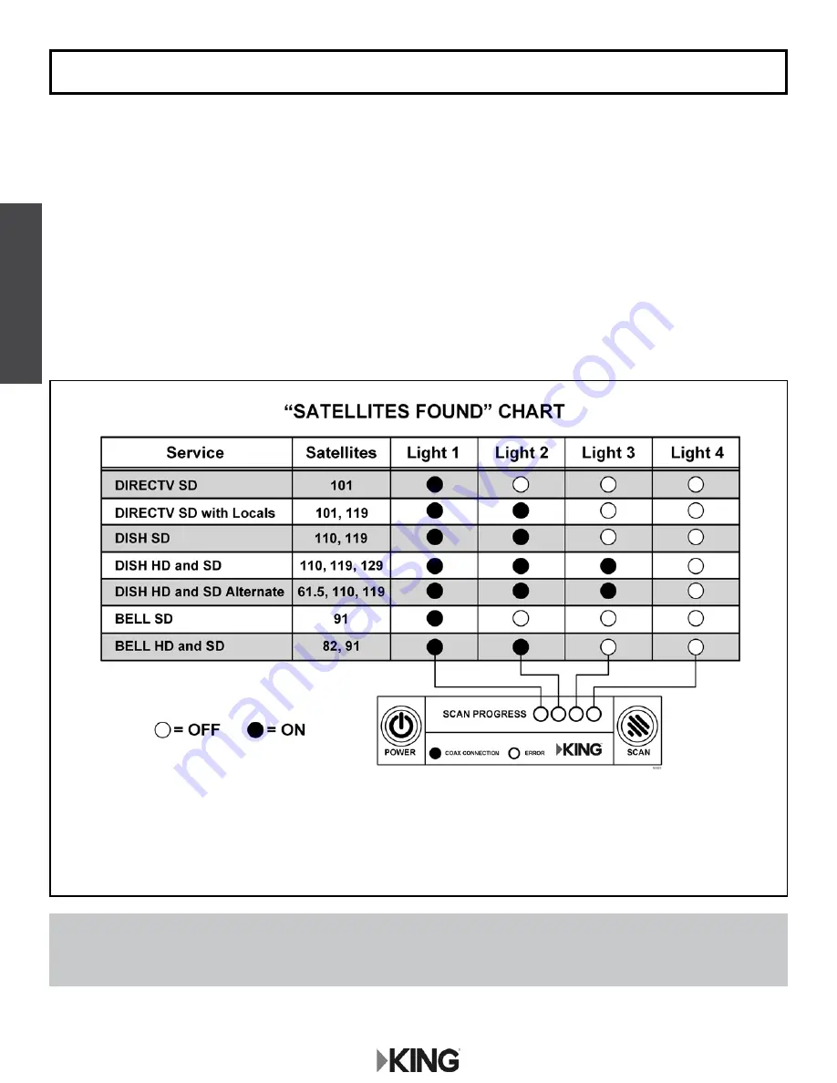
As satellites are located, the corresponding
SCAN PROGRESS
lights will turn on (see below).
•
When scan is complete, the appropriate lights will be on to show which satellites were found.
•
Wait for the program guide to download and then select your desired channel. Enjoy!
If you move the vehicle, you will have to reacquire the satellites by repeating the scan process. The KING Quest will
go into “sleep mode” after 15 minutes and the
COAX
CONNECTION
light will dim.
To turn the unit off at any time, press
POWER
for 5 seconds.
Use this chart to determine which satellites have been found.
NOTE:
The order of the lights corresponds to the order of the satellites listed.
Example for
DISH SD
: The 110 satellite corresponds to Light 1, and the 119
satellite corresponds to light 2.
Summary of Contents for VQ4100
Page 2: ......
Page 9: ...Page 7 Power Injector 3 4 SWM Only Receiver Connections ...
Page 10: ...Page 8 Power Injector 3 5 Troubleshooting Flowchart ...
Page 11: ...Page 9 Power Injector ...
Page 12: ...Page 10 Power Injector ...
Page 13: ...Page 11 Power Injector ...
Page 21: ...Page 19 This page intentionally left blank UC1000 Controller ...
Page 32: ...Page 30 4 8 Troubleshooting Flowchart UC1000 Controller ...
Page 33: ...Page 31 UC1000 Controller ...
Page 34: ...Page 32 UC1000 Controller ...
Page 35: ...Page 33 UC1000 Controller ...
Page 36: ...Page 34 4 9 Troubleshooting Flowchart Tailgater Mode UC1000 Controller ...
Page 37: ...Page 35 UC1000 Controller ...
Page 38: ...Page 36 UC1000 Controller ...
Page 39: ...Page 37 UC1000 Controller ...
Page 45: ...Page 43 This page intentionally left blank ...
Page 47: ...Page 45 Section 6 REPLACE ELEVATION MOTOR ...
Page 48: ...Page 46 Section 7 REPLACE AZIMUTH MOTOR AND POT ASSEMBLY ...
Page 49: ...Page 47 ...
Page 50: ...Page 48 Section 8 REPLACE MAIN AND TILT CIRCUIT BOARDS ...
Page 51: ...Page 49 ...
Page 53: ...Page 51 ...
Page 55: ......


