CHISEL & BIT
INSTALLATION/ADJUSTMENT
Chisel and Bit Installation
WARNING
: Make sure switch is in the
OFF
position and power cord is unplugged before
performing checks, adjustments, or setup procedures.
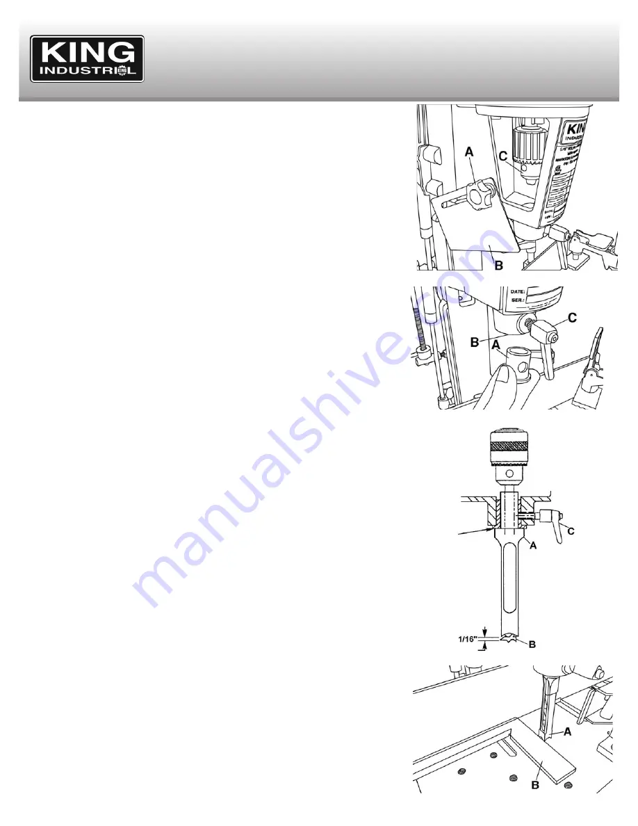
Loosen the two lock knobs (A) Fig.15 on both sides of the head and lower the covers (B)
to expose the chuck (C).
NOTE
: There are two different size chisel bushings provided. Determine which size fits the
chisel shank (5/8” or 3/4”) to be used and store the remaining one in a safe place for future
use.
Insert the appropriate chisel bushing (A) Fig.16 up through the hole in head (B), being sure
that round hole in the side of chisel bushing faces the front of machine. The lock knob (C)
must pass through this hole to secure chisel. Tighten the chisel bushing lock knob (C),
located on front of the head, until the chisel bushing is held up in place.
NOTE
: This lock knob should not become tight at this point. If it does, loosen it and retry,
making certain that the round hole in the side of the chisel bushing is lined up with the lock
knob.
Insert bit into chisel and insert chisel and bit up through hole in head assembly.
NOTE
: The opening in the side of the chisel should always be to the right or left, never to
the front or rear. The opening allows chips to escape during operation.
Push the chisel (A) Fig.17 up as far as possible into head, then lower chisel approximately
1/16". This setting is only temporary, the chisel will need to be repositioned against the
head once the bit is secure in place. Tighten lock knob (C) to hold chisel in position. Push
the drill bit (B) up through the chisel opening making sure that drill bit bottoms out in
chisel before bottoming out in chuck. Secure the bit in the chuck using the chuck key
supplied. Loosen lock knob (C) and push chisel up all the way into the head and retighten
lock knob. Refer to Fig.17.
NOTE
: Chisel was first lowered approximately 1/16" in the step above. The flat portion of
the bit should be adjusted to a minimum of 1/16" away from the bottom of the chisel. For
certain types of wood it may be necessary to increase this distance up to a maximun of
3/16" clearance. This assures having proper clearance between the cutting lips of the bit
and the points of the chisel.
Adjusting the Chisel Square with the Travel of the Table and the Fence
When the chisel is tightened in the machine, it must be square to the travel of the table and
the fence. First you must make sure the fence is set parallel to the travel of the table, the
easiest way to achieve this is to measure from the front edge of the table to both ends of
the fence.
Once you are certain the fence is parallel to the table, now you can proceed with setting
the chisel square with the fence. The easiest way to achieve this is to lower the head down
to bring the chisel (A) Fig.18 as close to the table as possible. Use the head height stop
bushing to hold it in this position. Place a square (B) against the fence and the side of the
chisel, loosen chisel lock knob, set the chisel square and and retighten lock knob.
Remember to have the chip ejection slot in the chisel to the side from which you will cut the
mortise.
Figure 16
Figure 17
Figure 15
Figure 18


