CONTROLS & ADJUSTMENTS
Adjusting Sliding Table Position
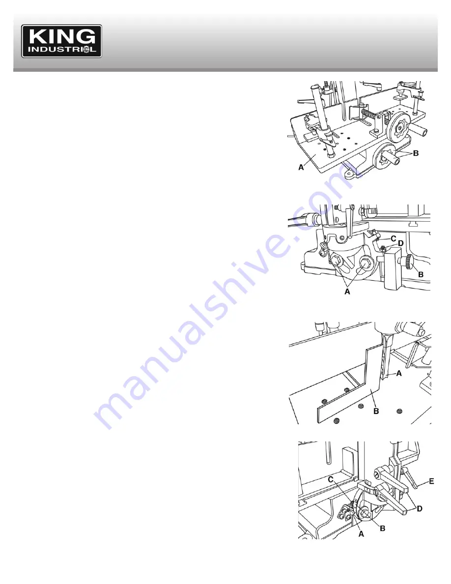
The sliding table (A) Fig.7 is very convenient if you plan on making multiple cuts in the
same workpiece, it allows you to move the sliding table over instead of unclamping and
repositioning your workpiece. To move the the sliding table to the right or left, turn the lower
handwheel (B).
Tilting Head (for specialized woodworking applications)
The head can be tilted from 0
0
to 30
0
toward the right or the left. To tilt the head, first begin
by holding the head with one hand. Then with the other hand, loosen both head fixing hex.
bolts (A) Fig.8 using the supplied 17mm open ended wrench.
Then pull out the stop pin (B) Fig.8 and move the head to the desired angle. Line up the
angle scale pointer (A) Fig.9 with the desired angle on the scale (B) Fig.9 and retighten
both head fixing hex. bolts.
If you desire to quickly adjust the head angle to 30
0
, for left tilt simply push the stop pin back
in until it comes into contact with positive stop set screw (C) Fig.8, for right tilts simply swing
the head to the right until the head casting comes in contact with the right side positive stop
set screw (C) Fig.9. If one or both positive stops do not give you a perfect 30
0
angle, they
can be adjusted, see section below for instructions.
Adjusting 0
0
and 30
0
Positive Stop Set Screws
The positive stop set screws (C,D-Fig.8 and C-Fig.10) are adjusted properly at the factory,
but after time, if you find that the angle is slightly off, an adjustment may be necessary.
To adjust the 0
0
positive stop set screw (D) Fig.8, make sure the stop pin (B) is positioned
below the 0
0
positive stop set screw as shown in Fig.8. Install a chisel and bit into the head
following the instructions in this manual.
Place a square (B) Fig.9 on the sliding table and against the chisel (A) Fig.9 and check if
the chisel is perfectly perpendicular to the square. If an adjustment is needed, loosen both
head fixing hex. bolts (A) Fig.8 using the supplied 17mm open ended wrench, tilt the head
until the chisel is perfectly perpendicular and retighten both head fixing hex. bolts. Loosen
the 0
0
positive stop hex. nut, and repostion the set screw against the stop pin and
retighten the hex. nut.
To adjust the 30
0
positive stop set screws (C) Fig.8 and Fig.10, use a 30
0
square or a
protractor and follow the same procedures above.
Swiveling Head (for specialized woodworking applications)
The head can be swiveled to the right or to the left up to 180
0
, it is important that you
remove the chisel and bit from the head before proceeding with this adjustment.
First loosen the two large lock handles (D) Fig.10, then tighten the small lock handle (E) to
widen the gap in the column sleeve casting. Swivel the head to the desired angle, loosen
the small lock handle and tighten the two large lock handles to lock the head in position.
Figure 7
Figure 8
Figure 9
Figure 10


