ASSEMBLY & ADJUSTMENTS
INSTALLING MITER GAUGE IN T-SLOT OF DISC TABLE
1. Slide the T-slot bar (A)
Fig.7 of the miter gauge assembly (B) into one end of the
T-slot (C) of the disc table (D).
Note: The miter gauge can be used in either direction in the t-slot of the disc table,
use the most effective direction depending on the operation. Keep in mind, when
sanding using the sanding disc, the workpiece must be positioned on the side of the
disc which rotates downward.
2. To adjust the angle of the miter gauge (B) Fig.7, loosen lock knob (E), pivot miter
gauge to the desired angle, and retighten lock knob. For precise angles, use a
combination square to set the angle.
INSTALLING BELT TENSION LEVER
1. Install the belt tension lever and knob (A) Fig.8 into the threaded hole on the belt
tension hub (B).
ADJUSTMENTS
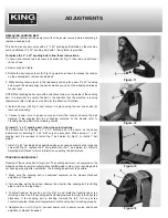
TILTING BELT TABLE/SETTING TABLE 90
0
The belt table (A)
Fig.9 can be tilted downward from 0-45
0
. To adjust and set the belt
table angle to a perfect 90
0
angle:
1. Loosen the belt table lock handle (B) Fig.9, now the belt table (A)
can be tilted and
locked at the desired angle.
2. To set the belt table at a perfect 90
0
angle to the sanding belt, loosen lock handle
(B) Fig.9, then position a square (C) on the table and up against the sanding belt.
Adjust the angle of the belt table until the sanding belt and belt table are square,
retighten lock handle (B).
TILTING DISC TABLE/SETTING TABLE 90
0
The disc table (A)
Fig.10 can be tilted downward from 0-45
0
. To adjust and set the
disc table angle to a perfect 90
0
angle.
1. Loosen both disc table lock handles (B) Fig.10, now the disc table (A)
can be tilted
and locked at the desired angle.
2. To set the disc table at a perfect 90
0
angle to the sanding disc, loosen lock handles
(B) Fig.10, then position a square (C) on the table and up against the sanding disc.
Adjust the angle of the disc table until the sanding disc and disc table are square,
retighten lock handles (B).
3. If the disc table is square with the sanding disc, but the angle indicator (D) is not
aligned with the 0
0
mark of the trunnion scale (E), loosen the angle indicator screw
and reposition the angle indicator to line up with the 0
0
mark of the trunnion scale
(E).
Figure 7
Figure 8
Figure 9
Figure 10


