background image

LUBRICATION & MAINTENANCE

LUBRICATION

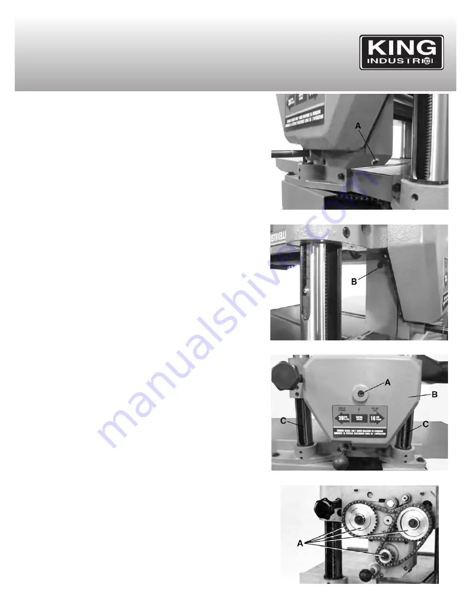
The gear box oil should be changed after the first 20 hours of operation as part
of the normal break-in procedure, and then once a year using automotive
grade gear oil (80W-90W). The gear box drain plug (A) Fig.34 is located at the
bottom of the gear box. The oil fill and level plug (B) Fig.35 is located on the
side of the gear box.

The proper oil level is reached when it reaches the bottom of the oil fill and
level plug hole.

The four raising lead screws (C) Fig.36 should be lubricated as required using
a common grease.

Periodically remove cap screw (A) Fig.36 and side cover (B). Thoroughly
clean chains and sprockets (A) Fig.37 and lubricate using a light machine oil.
Replace side cover.

Cleaning maintenance

Regularly clean the planer parts to keep them in optimal condition, vacuum
excess wood chips and sawdust. Excessive dust and wood chips in the motor
could cause excessive heat. Every effort should be made to prevent foreign
material from entering the motor. A visual inspection should be made at
frequent intervals. Accumulations of dry dust can usually be blown out to
prevent the interference with normal motor ventilation. To remove dust, blow
off motor with a low pressure air hose.

The operator performing this cleaning function should wear safety glasses
and a filter mask. If any servicing (other than the above cleaning) becomes
necessary, it should be performed by an authorized service centre.

Daily maintenance:

- Clean unpainted surfaces of the table and relubricate.

Weekly maintenance:

- Clean cutterhead.
- Lubricate the lead screws (C) Fig.36 of the four columns.

Monthly maintenance:

- Inspect V-belts for tension.
- Clean dust build-up on motor.
- Lubricate lead screws.
- Lubricate chain.

Yearly maintenance:

- Change gear box oil (80W-90W automotive grade gear oil).

FIGURE 34

FIGURE 35

FIGURE 36

FIGURE 37

Summary of Contents for KC-382CFX

Page 1: ...INSTRUCTION MANUAL MODEL KC 382CFX COPYRIGHT 2013 ALL RIGHTS RESERVED BY KING CANADA TOOLS INC 15 INDUSTRIAL PLANER 03 2013...

Page 2: ...nada shall in no event be liable for death injuries to persons or property or for incidental special or consequential damages arising from the use of our products To take advantage of this limited war...

Page 3: ...clean for best and safest performance Follow instructions for lubricating and changing accessories 15 DISCONNECT TOOLS Before servicing when changing accessories or attachments 16 AVOID ACCIDENTAL ST...

Page 4: ...N PROPER GROUNDING OF YOUR PLANER DO NOT REMOVE OR ALTER THE GROUNDING PRONG IN ANY MANNER WARNING IF NOT PROPERLY GROUNDED THIS PLANER CAN CAUSE ELECTRICAL SHOCK PARTICULARLY WHEN USED IN DAMP LOCATI...

Page 5: ...er 18 Chip breaker 19 Cutterhead 20 Outfeed roller SPECIFICATIONS KC 382CFX 15 INDUSTRIAL PLANER TECHNICAL INFORMATION Motor 3HP 240V 18Amp 1 Phase 60Hz Power transfer 3 V belts Capacities Minimum Len...

Page 6: ...and lowering shaft using a large washer and hex nut B supplied 3 Assemble handle C Fig 5 to handwheel A as shown 4 Loosen two head locking knobs one of which is shown at D Fig 5 and turn handwheel clo...

Page 7: ...6 wide is 3 16 when the stock is run through the planer on one side or the other of the cutterhead A limiter A Fig 9 is provided to limit the depth of cut to 1 8 on stock wider than 6 POWER FEED CONTR...

Page 8: ...ts must be tensioned after the first 16 hours of operation or your V belts will slip or burn out Always replace the V belts with a matched set of three V belts or the belt tension may not be even caus...

Page 9: ...the motor forward WARNING THE CUTTERHEAD AND KNIVES ARE NOW EXPOSED AND CARE SHOULD BE TAKEN AS THE KNIVES ARE VERY SHARP 4 To check and adjust the knives proceed as follows A Carefully place the kni...

Page 10: ...ting with the end screws first then the centre screws until the knife is securely held in the cutterhead Tighten the remaining two knives in the same manner 5 If the knives are removed for sharpening...

Page 11: ...he table directly under the cutterhead as shown Using 0 020 feeler gauge B placed on top of the gauge block raise or lower the head assembly until one of the knives just touches the feeler gauge when...

Page 12: ...he gauge block Then tighten hex nut D 6 Repeat this adjustment with the gauge block on the opposite end of the infeed roller ADJUSTING HEIGHT OF OUTFEED ROLLER The outfeed roller is adjusted at the fa...

Page 13: ...hich aid in feeding stock by reducing friction and turn as the stock is fed through the planer It is not possible to give exact dimensions on the proper height setting of the table because each type o...

Page 14: ...table 5 If the head casting is not parallel to table unassemble the planer from its enclosed stand and then tilt planer on its side as shown in Fig 32 Remove hex bolt C and loosen hex bolt D Fig 32 w...

Page 15: ...xcess wood chips and sawdust Excessive dust and wood chips in the motor could cause excessive heat Every effort should be made to prevent foreign material from entering the motor A visual inspection s...

Page 16: ...not parallel with table 6 Pitch or glue build up on components 1 High wood moisture or wet surface 2 Dull knives 1 Feeding workpiece too fast 2 Chipbreaker set unevenly 3 Knives installed unevenly 4 W...

Reviews: