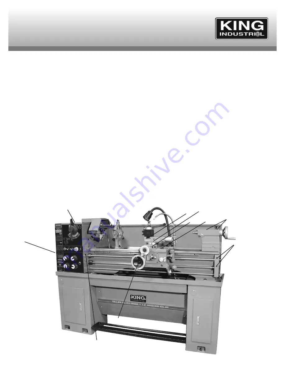
COOLANT SYSTEM &
LUBRICATION POINTS
Using the Coolant System
It is suggested to use the coolant system during operations involving
high speed cutting. Excessive heat and damage to your cutting tool will
be avoided if the coolant system is on with the spout directed towards
the cutting tool and the work area during the cutting operation.
The coolant system operates by recycling the coolant flow from the
coolant pump up through the coolant spout, then falls into the chip tray
and drains back down to the coolant pump and the cycle is repeated.
To fill the system with coolant, simply pour coolant into the chip tray, it
will flow down into the coolant bucket. Be careful not to overflow.
The amount of flow is controled by a valve at the base of the coolant
spout. For maximum flow, open the valve completely.
Lubrication Points
Before operating the metal lathe,
check the oil level and lubricate all
sliding surfaces such as the dovetail slot, half nut, worm gear,
leadscrew, feed rod, handle rod, tailstock quill before and after
operating. Follow the main lubrication points illustrated below.
Note: Headstock lubrication point (1). After running for the first 3
months, change the oil. Change oil once a year after first initial oil
change. To drain oil from the headstock, remove left end cover and the
gear change swing arm to gain access to the drain hole, drain oil and
then open top oil cover and fill oil until it reaches the 3/4 mark on the
oil level indicator. The bearings should be completely immersed in oil.
•Carriage lubrication point (5). The carriage is filled with machine oil
through the filling plug on the top of the carriage. Oil level should be
checked regularly. Change oil after the first 3 months and once every
year after.
•Gear Change lubrication point (3). Lubricate the change gears with
thick machine oil or grease once a month.
•A light oil should be used on the bedway and all other reflective parts
such as the tailstock quill.
Lubrication Points
Headstock lubrication point (1)
.
Gear Box lubrication point (2).
Gear Change lubrication point (3).
Saddle lubrication point (4).
Carriage lubrication point (5).
Handwheel lubrication point (6).
Leadscrews & Bracket lubrication points (7).
Tailstock lubrication points (8).
Tool Post Slide lubrication point (9).
Top slide set screw lubrication point (10).
5
4
8
7
6
1
3
2
FIGURE 18
9
10


