background image

AdJUSTMeNTS & 

CHANGING SANdING beLT

SANdING beLT TrACKING AdJUSTMeNT

Warning! 

Disconnect power from power source before attempting to adjust this

edge sander.

To prolong the life of the sanding belt and to avoid any slippage of the belt off the

drums, proper sanding belt tracking is important to maintain the sanding belt 

running straight on the drums. To adjust sanding belt tracking:

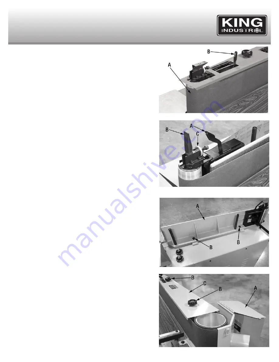
1) Make sure the sanding belt (A) Fig.8 is properly tensioned, the tension lever

(B) must be positioned to the right as shown. 

2) Turn the edge sander On for a few seconds and observe the tracking of the

sanding belt.

3) If an adjustment is needed, move the tension lever (A) Fig.9 completely to the

left “loose” position as shown.

4) Lift the belt tracking locking lever (B) Fig.9 and turn the adjustment wheel (C)

to  adjust  belt  tracking.  Turn  adjustment  wheel  clockwise  to  track  belt 

downwards on the roller, turn counterclockwise to track belt upwards on the

roller.

5)  Lower  belt  tracking  locking  lever  (B)  Fig.9,  move  the  tension  lever  (A) 

completely to the right “tensioned” position. Turn the edge sander On for a few

seconds and observe the tracking of the sanding belt. Repeat until sanding belt

is tracking properly.

AdJUSTING THe STeeL PLATeN

Warning! 

Disconnect power from power source before attempting to adjust this

edge sander.

The steel platen (A) Fig.10 should be positioned 1/8” to 1/4” in front of the drive

roller and the idle roller. The steel platen is set properly at the factory but after

time an adjustment may be needed. To adjust the position of the steel platen:

1) Remove the sanding belt, refer to the next section below “Changing Sanding

Belt” for instructions.

2) Loosen the two hex. bolts (B) at the rear of the steel platen.

3) Using a straightedge or a combination square, position the steel platen from

1/8” to 1/4” in front of both rollers.

4) Retighten the two hex. bolts (B) at the rear of the steel platen and reinstall 

sanding belt.

CHANGING THe SANdING beLT

Warning! 

Disconnect power from power source before attempting to change the

sanding belt.

A sanding belt should be changed when it has worn out. Follow these instructions

to change a sanding belt:

1) Open the right side safety guards (A) Fig.11 by unclipping the two retaining clips

and flipping the safety guards backwards.

2) Loosen and remove the two lock knobs (B) and then remove the belt access

cover (C).

FIGUre 8

FIGUre 9

FIGUre 10

FIGUre 11

Summary of Contents for KC-108-OSC

Page 1: ...INSTrUCTION MANUAL MOdeL KC 108 OSC 6 x 10⁸ OSCILLATING edGe SANder COPYRIGHT 2016 ALL RIGHTS RESERVED BY KING CANADA TOOLS INC 04 2017 ...

Page 2: ...d lack of maintenance King Canada shall in no event be liable for death injuries to persons or property or for incidental special or consequential damages arising from the use of our products To take advantage of this limited warranty return the product at your expense together with your dated proof of purshase to an authorized King Canada service centre Contact your retailer or visit our web site...

Page 3: ...glasses only have impact resistant lenses they are NOT safety glasses Also use a face or dust mask if cutting operation is dusty 13 dON T OVerreACH Keep proper footing and balance at all times 14 MAINTAIN MACHINe WITH CAre Keep machine clean for best and safest performance Follow instructions for lubricating and changing accessories 15 dISCONNeCT MACHINe Before servicing when changing accessories ...

Page 4: ...ith this Edge Sander and must be purchased at your local hardware store The 220V plug must be a CSA listed plug suitable for 220V operation This plug is illustrated in Fig 1 Contact your authorized service centre or qualified electrician to install the plug eXTeNSION COrdS WArNING IT IS NOT RECOMMENDED TO USE AN ExTENSION CORD BUT IF IT IS NECESSARY READ THE FOLLOWING The use of any extension cord...

Page 5: ...x cover 12 Magnetic safety switch 13 Enclosed cabinet 14 Leveling Fixing bolt 1 of 4 15 Main table height adjusting knob 16 Main table lock knob 1 of 2 17 End table support 18 End table lock handle 19 End table SPeCIFICATIONS MODEL KC 108 OSC Belt 6 x 10⁸ Oscillating stroke 1 4 Table size front 37 x 7 3 4 Table size side 19 x 11 3 4 Belt speed 3 150 SFPM Motor 10 Amp 220V Voltage 220V 1 phase 60 H...

Page 6: ...life 6 The front main table A Fig 5 can also be inclined left or right to allow sanding irregular workpieces Loosen the two lock knobs B and raise or lower one end of the front main table Retighten the two lock knobs B to secure the table position INSTALLING ANd AdJUSTING THe HeIGHT OF THe eNd TAbLe 1 Locate the end table A Fig 6 inside the enclosed cabinet 2 The end table support B needs to be un...

Page 7: ...onds and observe the tracking of the sanding belt Repeat until sanding belt is tracking properly AdJUSTING THe STeeL PLATeN Warning Disconnect power from power source before attempting to adjust this edge sander The steel platen A Fig 10 should be positioned 1 8 to 1 4 in front of the drive roller and the idle roller The steel platen is set properly at the factory but after time an adjustment may ...

Page 8: ...uire replacement once visible signs of wear are apparent To change graphite pad 1 Following the instructions for removing the sanding belt 2 Pull the old graphite pad A Fig 13 off the steel platen A strong solvent may be required to unglue the graphite pad from the steel platen 3 Install a new graphite pad on the steel platen Some graphite pads have adhesive backings some will require using contac...

Reviews: