background image

ADDITIONAL SAFETY INSTRUCTIONS  

FOR YOUR JOINTER

READ AND UNDERSTAND INSTRUCTION MANUAL 
BEFORE OPERATING JOINTER 

1.  DO NOT ALTER OR MISUSE THE TOOL. 


These tools are precision built. Any alteration or modification 

not specified is misuse and may result in dangerous conditions.  

2. AVOID GASEOUS AREAS. 

Do not operate electric tools in gaseous or explosive                  
environnements. Motors in these tools normally spark and may 
result in dangerous conditions. 

3. BEFORE CONNECTING TO THE POWER SOURCE. 
    

Make sure the voltage supplied is the same as that specified 

on the nameplate of the tool. A power source with a voltage 
greater than that specified for the tool can result in serious injury 
to the operator, as well as damage to the tool. If in doubt, DO

NOT

PLUG

IN

TOOL. Using a power source with a voltage less 

than the nameplate rating is harmful to the motor. 

4. STABILITY OF THE JOINTER. 

Your jointer must be bolted securely to a stand or a workbench. 
In addition, if there is any tendency for the jointer to tip over or 
move during certain operations, such as cutting long, heavy 
boards, bolt your jointer stand or workbench to the floor. 

5. LOCATION. 

This jointer saw is intended for indoor use only.


6. MISSING OR MALFUNCTIONING PARTS. 

If any part of the jointer is missing, malfunctioning, has been 
damaged or broken...such as the motor switch, or other           
operating control, a safety device or the power cord...cease    
operating immediately until the particular part is properly 
repaired or replaced.


7. CLEARING THE TABLE OF ALL OBJETS. 

Never turn your jointer on before clearing the table of all 

objects (tools, scraps of wood...) except for the workpiece and 
related feed and support devices for the operation planned. 

8. AVOID AWKWARD HAND POSITIONS. 

A sudden slip could cause a hand to move into the blade. 

9. FEEDING SPEED. 

Do not feed the material too fast while cutting. Only feed 

the material fast enough so that the blade will cut. Keep fingers 
away from the blade.


10. 

DO NOT

 perform any layout, assembly or setup work on 

the table while the jointer is operating.


11. Never

 perform a jointing or planing operation with       

cutterhead or drive guard removed.  

12. Never

 make a jointing or planing cut deeper than 1/8

˝

.  

13. Always use hold downs or push blocks

 for jointing 

material narrower than 3

˝

 or planing material thinner 

than 3

˝

.  

14. Never 

joint or plane material less than 10

˝

 long.  

15. ALWAYS KEEP HANDS AND FINGERS AWAY FROM 

CUTTERHEAD.


16. Disconnect machine

 from power source before making 

repairs or adjustments.  

17. Do not operate

 while under the influence of drugs,     

alcohol, or medication. 


Summary of Contents for 8" Jointer KC-203C

Page 1: ...8 JOINTER INSTRUCTION MANUAL COPYRIGHT 2002 ALL RIGHTS RESERVED BY KING CANADA TOOLS INC MODEL KC 203C...

Page 2: ...gh quality and durability standards KING CANADA warrants to the original retail consumer a 2 year limited warranty as of the date the product was purchased at retail and that each product is free from...

Page 3: ...ry rings watch because they could get caught in moving parts Non slip footwear is recommended Wear protective hair covering to contain long hair Roll up long sleeves above the elbows 12 ALWAYS WEAR SA...

Page 4: ...se only 6 MISSING OR MALFUNCTIONING PARTS If any part of the jointer is missing malfunctioning has been damaged or broken such as the motor switch or other operating control a safety device or the pow...

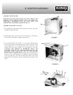
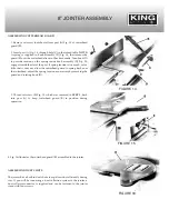
Page 5: ...up three holes F and L Fig 2 on top stand with three holes located at the bottom of the jointer base and fasten the jointer to the base with three 3 8 16 x 2 long hex head screws G Fig 3 six flat wash...

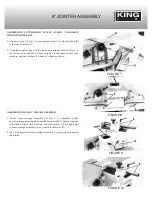
Page 6: ...be moved in or out on the motor shaft or the motor can be moved by loosening four mounting screws two of which are shown at E Fig 6 After adjustment is made tighten the four mounting screws or the se...

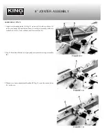
Page 7: ...socket head screws lock washers and flat washers F three of which are shown ASSEMBLING FENCE CARRIAGE ASSEMBLY 1 Fasten fence carriage assembly A Fig 9 to cutterhead pulley guard carriage mounting br...

Page 8: ...in fence carriage B and fasten fence to carriage assembly with two socket hex screws lock washers and flat washers D 2 Fig 12 illustrates the fence A properly mounted to carriage assembly B 3 Thread t...

Page 9: ...that it does not allow the cutterhead guard to spring back over the cutterhead adjust the spring tension as necessary by removing the guard and rotating knob D 3 Thread set screw E Fig 15 which was r...

Page 10: ...MAINTAIN PROPER GROUNDING OF YOUR JOINTER DO NOT REMOVE OR ALTER THE GROUNDING PRONG IN ANY MANNER CHANGING VOLTAGE The motor supplied with your King Canada 8 jointer is a dual voltage 110 220V single...

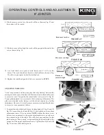
Page 11: ...feed table position of the infeed table in relation to the cutting circle is indicated on scale E Fig 20 NOTE Maximum depth of cut with this jointer is 1 2 which can be accomplished in cuts of 1 8 inc...

Page 12: ...cribed in section INFEED TABLE ADJUSTMENTS 4 Place a steel straight edge on the outfeed table extending over the cutterhead as shown in Fig 24 5 Carefully rotate the cutterhead by hand The knives shou...

Page 13: ...djusted at the factory and should not require any further adjustment However if it ever becomes necessary to adjust the gibs due to excessive wear proceed as follows 1 To adjust the infeed table gib l...

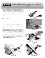
Page 14: ...esired position tighten locking handle A As the fence is moved across the table the rear cutterhead guard C Fig 34 extends over the knives in back of the fence for operator safety 2 To tilt the fence...

Page 15: ...ve stop is necessary loosen locking handle D Fig 38 and lock nut M Rotate adjustment screw N until you are certain the fence is 450 outward the table 7 Tilt the fence G Fig 39 inward as far as it will...

Page 16: ...g a straight edge J on the rear table adjust the height of the rear table until it is 0 060 above the cutting head diameter as shown 12 Lock the rear table in position and remove the feeler gage 13 Lo...

Reviews: