


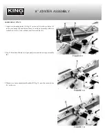
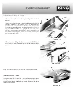


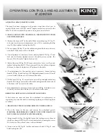


8. If the knives are set too low, the result will be as shown in Fig. 27, and
the surface will be curved.
9. If the knives are set too high, the work will be gouged at the end of the
cut, as shown in Fig. 28.
10. As a final check, run a piece of work slowly over 6
˝
to 8
˝
over the
knives. The work should rest firmly on both tables as shown in Fig.
29, with no open spaces under the finished cut.
11. Replace the cutterhead guard which was removed in
STEP 2.
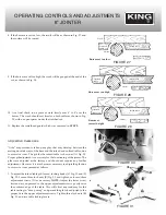
ADJUSTING TABLE GIBS
“Gibs” are provided to take up any play that may develop between the
mating dovetail ways of the base and the infeed and outfeed tables, due
to excessive wear. The gib for the infeed table is shown at (A) Fig. 30.
Proper gib adjustment is necessary for the functioning of the jointer. The
gibs were adjusted at the factory and should not require any further
adjustment. However, if it ever becomes necessary to adjust the gibs due
to excessive wear, proceed as follows:
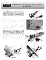
1. To adjust the infeed table gib, loosen locking knobs (C) Fig. 31 and (F)
Fig. 32. Loosen three lock nuts (B) Fig. 31, and tighten or loosen three
adjustment screws (D) as necessary.
NOTE:
Adjust the lower screw
first and as you proceed to the upper adjustment screws, gently raise
the outboard edge of the table. This will offset any tendency for the
table casting to “droop or sag” and permit the gib to be adjusted to the
proper fit to the upper adjustment screws. Tighten three lock nuts (B)
Fig. 31, and two table locking levers.
OPERATING CONTROLS AND ADJUSTMENTS
8” JOINTER
FIGURE 27
FIGURE 28
FIGURE 29
FIGURE 30
FIGURE 31
Outfeed
table
Work
Infeed table
Cutter
Knives set too low
Outfeed
table
Work
Infeed table
Cutter
Knives set too high
Outfeed
table
Work
Infeed table
Cutter
Knives at
correct height


