background image

A

Page 19 / 24

Datasheet 1.10-60.015-01-EN

RBW322-FTL

Product Description

Issue 2016-05-16 ab V2.60

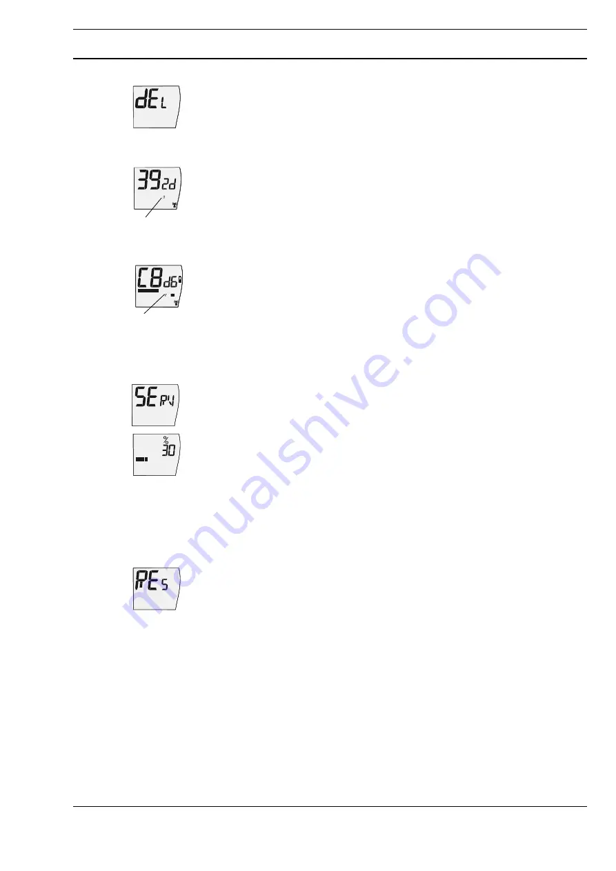
Delete Function

See chapter "Deleting the wireless partner on the RBW322-FTL", Page 22.

Status display for taught-in radio partners

If no radio partners have been taught-in, this status display does not appear.
If radio partners have been taught-in, the following messages are displayed:

 EnOcean system gateway

EnOcean ID (the last four hexadecimal digits of the system gateway’s EnOcean ID, here 
392d), radio status indicator, assigned radio partner (1)  0 (system gateway)

 Radio actuator

EnOcean ID (the last four hexadecimal digits of the radio actuator’s EnOcean ID, here 
C8D6), setpoint (bar indicator, here 50 %), radio status indicator,
assigned radio partner (1) 1 - 4 (radio actuator), if applicable, the Window Open 
Detection and battery indicator of the radio partner

 Turning the knob displays these status messages for every taught-in radio partner 

    in sequence.

Valve Position for Service Purposes

 In the service level, use the knob to select the “Valve position for service purposes”

SERV

 function.

 Press the knob.

 Turn the knob to select the desired valve position. 

     Confirm the setting by pressing the knob.
     The display switches to the initial display.
Confirming the valve position sends the set valve position to all of the taught-in radio 
actuators with the next communication cycle.
Room temperature control is inactive for one transmission/reception interval.

Restore Default Settings

 In the service level, use the knob to select the “Restore default settings”

RES

 function.

 Press the knob. The display flashes.

 Press the knob again. The “Restore default settings” function is 

    carried out.
All settings are restored to the default settings, the taught-in radio partners are deleted 
and the device switches to its initial state (display is switched off, see page 11).  

1

1

Summary of Contents for RBW322-FTL

Page 1: ...EP D2 10 01 for connection to an EnOcean gateway In combination with the MD15 FTL xx the RBW322 FTL constitutes a functional unit for controlling the room temperature You can find information about the protocol description on the EnOcean Technology website http www enocean alliance org en enocean_standard Content Page Important Information Regarding Product Safety 2 Technical Data 3 Dimensions 4 R...

Page 2: ...operator to comply with local regulations Mounting installation and commissioning work on the devices may only be carried out by qualified technicians Qualified technicians are persons who are familiar with the described product and who can assess given tasks and recognize possible dangers due to technical training knowledge and experience as well as knowledge of the appropriate regulations Legend...

Page 3: ...mperature units selected 7 0 35 0 C in 0 5 K increments or 44 95 F in 1 F increments Controls Push and rotary knob for setting setpoint party mode vacation mode weekly schedule time date display options e g 12 24 hour display and service data Occupancy button manually switch between present absent Interfaces technoLink radio interface Radiogram EnOcean radiogram bidirectional Frequency 868 3 MHz D...

Page 4: ...A Page 4 24 Product Description RBW322 FTL Datasheet 1 10 60 015 01 EN Issue 2016 05 16 ab V2 60 Dimensions 3 6 3 5 0 4 0 4 0 8 0 2 6 5 0 3 R 1 8 0 1 ...

Page 5: ...rectional and includes an intelligent synchroni zation process If the radio communication between the RBW322 FTL and the MD15 FTL xx is interrupted an internal resynchronization procedure starts automatically Radio connection Gateway operation Gateway and pair operation Pair operation EnOcean Gateway RBW322 FTL EnOcean Gateway RBW322 FTL MD15 FTL RBW322 FTL MD15 FTL ...

Page 6: ...materials and screening elements e g suspended ceiling elements installation shafts fire doors etc must be taken into consideration during planning NOTICE Elevated humidity increases natural signal damping NOTE Recommendation Plan radio paths horizontally on a single level with max 30 m between the trasmitting and receiving modules Designed only for use in rooms Observe minimum distances to potent...

Page 7: ...tallation location can be changed and optimized at any time without additional effort Mounting The installation location must have sufficient lighting using the device in unlit rooms such as interior kitchens bathrooms shortens the length of the maintenance cycle The solar cell is optimized for indoor use and it works particularly efficiently with diffuse lighting NOTICE Prolonged illumination at ...

Page 8: ...8 24 Product Description RBW322 FTL Datasheet 1 10 60 015 01 EN Issue 2016 05 16 ab V2 60 Wall mounting Flexible adhesive mounting with double sided transparent adhesive strips Removal 1 2 3 4 5 6 7 1 2 3 4 5 ...

Page 9: ...d malfunction message see page 22 12 24 hour display or the number of the usage time 6 Radio communication indi cator Radio symbol visible Radio symbol not visible Radio symbol flashing Radio communication present at least one radio partner has been taught in No radio communication present no radio partners have been taught in or all radio partners are malfunctioning Radio telegram in transmission...

Page 10: ...witching point start time for comfort mode Item Designation Explanation 1 Display Displays information regarding the current status 2 Push and rotary knob Turn set value e g setpoint Turn counterclockwise reduce value Turn clockwise Increase value Press change levels or confirm display setting 3 Solar cell Generates energy for the room control module 4 Magnetic contact below the housing Switches t...

Page 11: ...cupancy button for approximately 5 s switches summer mode on or off Manually switching between comfort and economy mode You can manually switch between comfort mode and economy mode and vice versa by pressing the Occupancy button This is displayed by the comfort mode or economy mode icons The Auto icon also disappears from the display NOTE The manually adjusted operating mode remains active until ...

Page 12: ...ial display A new setpoint can also be applied by pressing the push and rotary knob briefly Manuall override will also make the Auto symbol disappear NOTE The manually adjusted setpoint remains active until the next usage time status change The sepoints for comfort mode and economy mode which were set on the configuration level become active then see page 16 and the Auto symbol is displayed again ...

Page 13: ... usage time extension Set the end time for party mode usage time extension turning the knob The selected comfort mode extension usage time extension is shown in the display by the bar indicator Confirm the entry by briefly pressing the knob The display switches back to the initial display The comfort mode extension is effective immediately and comfort mode is switched on The activated party mode i...

Page 14: ...f the vacation Confirm the setting by pressing the knob The display switches back to the initial display Vacation mode begins on the set start date at 00 00 midnight and ends on the set end date at 00 00 midnight If a vacation time is set and has not yet begun the icon is shown on the initial display If vacation mode is active the vacation end date and the icon are shown on the display If vacation...

Page 15: ...ond usage time Set the second third and fourth usage times if desired The setting procedure is the same as for the first usage time block The display also shows which usage time block 1 is set The set utilization times will be saved after 10 s of idle time without further input when 4 utilization times were entered or end time start time The usage times of the current day are shown by the bar indi...

Page 16: ...g the knob Setting the time and date Press the knob for 3 s Use the knob to select the Time Date function TIME and press the knob The hour minutes year month and day can then be set in sequence The values to be set are always flashing Set the time Set the hour Confirm setting by pressing the knob Set the minutes Confirm setting by pressing the knob Set the year Confirm setting by pressing the knob...

Page 17: ...l display Default setting Initial display temperature Setting the 12 24 hour display Press the knob for 3 s Use the knob to select the 12 24 hour display function 24h and press the knob Set 12 or 24 hour display Confirm the setting by pressing the push and rotary knob If the 12 hour display 1 is activated an additional A for AM or P for PM is shown in the display Default setting 24h Switching the ...

Page 18: ... room control module changes to the service level Using a magnet Briefly press the magnet against the upper right hand side of the device see figure The room control module changes to the service level The following functions are available on the service level Registration Function Delete Function Status display for taught in radio partners Valve position for service purposes Restore default setti...

Page 19: ...dicator of the radio partner Turning the knob displays these status messages for every taught in radio partner in sequence Valve Position for Service Purposes In the service level use the knob to select the Valve position for service purposes SERV function Press the knob Turn the knob to select the desired valve position Confirm the setting by pressing the knob The display switches to the initial ...

Page 20: ...he specific settings and functions of the RBW322 FTL In addition to these instructions the product descriptions of the MD15 FTL xx radio partner and EnOcean gateway must also be observed Select service level see page 18 Use the knob to select the Teach in function T IN Teach in wireless actuator Up to 4 MD15 FTL xx radio actuators can be taught in on the RBW322 FTL Use the knob to select the Teach...

Page 21: ...n NOTE After a successful teach in process the device ID of the radio partner is stored in the SolarFunk room control module The teach in process does not need to be performed again when the battery is changed If the teach in process fails the radio symbol is not visible on the display The teach in process must be performed again or the radio communication path must be checked See chapter General ...

Page 22: ... of time the display switches to This warning disappears once the communication to the missing wireless part ner is re established If the wireless communication to all taught in wireless partners is interrupted the wireless icon is no longer displayed Wireless communication with at least one taught in MD15 FTL xx wireless part ner has been interrupted for more than four hours and a resynchronizati...

Page 23: ...s see p 19 The Δ8 icon disappears from the display Register the radio partner again The RBW322 FTL has a serious malfunction if the Δ8 icon continues to appear It should be checked by an authorized service technician System time The RBW322 FTL s internal system time is monitored constantly The Δ3 icon appears on the display if a system time malfunction is detected in the RBW322 FTL Reset the time ...

Page 24: ...Savings Time Flag bit When activating deactivating this function the RBW322 FTL does not automatically detect whether the time should be adjusted straight away or not The time should be synchronized immediately after making this kind of changes Date and Time Setting If the defined validity ranges are exceeded the dates and times transmitted by the gateway are rounded up or down to the valid ranges...

Reviews: