


63
2) Built-in TCP/IP protocol stack
3) Built-in 10 bit high precision ADC
4) Built-in TR switch, balun, LNA, power amplifier and matching network
5) Built-in PLL, voltage regulator and power management components, +20dBm output power in 802.11b
mode
6) A-MODU\A-MSDU aggregation and 0.4s guard interval
7) [email protected], zhichi WPA/WPA2 security mode
8) Support Smart Config function (including Android and iOS devices)
9) HSPI, UART, I2C, I2S, IR Remote Control, PWM, GPIO
10) Deep sleep keeps current at 10uA and shutdown current is less than 5uA
11) Wake up, connect and transfer packets within 2 ms
12) Standby power consumption is less than 1.0mW (DTIM3)
13) Operating temperature range: -20 ° C -85 ° C
4.9.3 Wifi Module Test Experiment Steps
1) Open the supporting information, find the folder
“
ESP-M2-Wifi Module\Wifi module test APP
installation package
”
installation package and open it. Install the test software “TCP
-
Test.apk”
in the
directory to the mobile phone (currently only supported in Android system) On the phone).
2) Open data
“
ESP-M2-Wifi Module\WifiModule_Test\WifiModule_Test.
ino”
3) Burn the WifiModule_Test.ino program to BLE-UNO R3; align the serial port pins of the Wifi module
with the mother socket on the Arduino-UNO R3 main board and insert it; connect the Bluetooth module to
the picture shown in Figure 4-9-2. Yes, the connection method is as follows: the VCC port of the ESP-M2
Wifi module is connected to the positive pole of the 5V DC power supply, the GND port is connected to the
negative pole of the power supply, the RXD port is connected to the TXD port of the Arduino expansion
board, and the TXD port is connected to the RXD port of the Arduino expansion board.
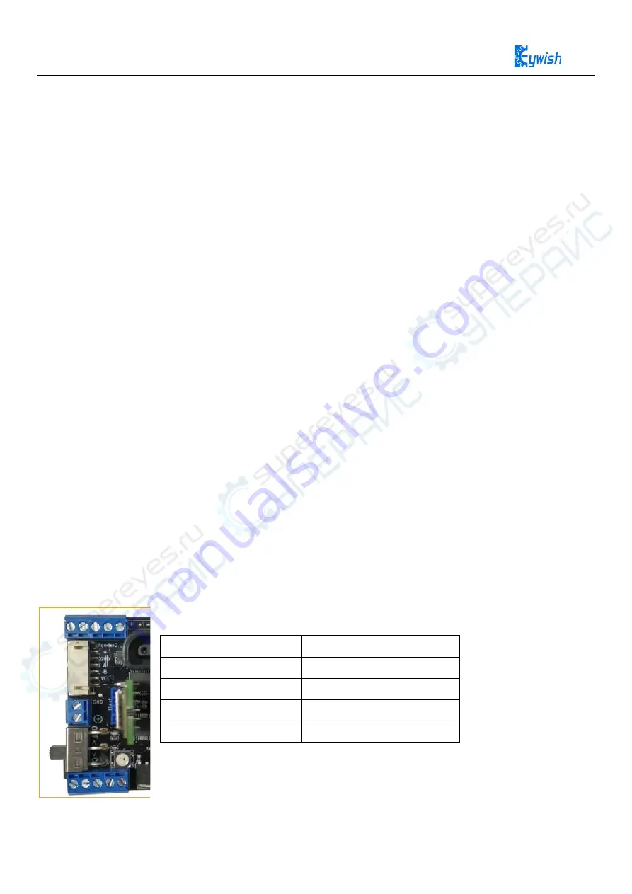
Figure 4-9-2 Wifi module connection location
ESP-M2
Arduino UNO
VCC
VCC
GND
GND
TXD
RXD
RXD
TXD


