Installation Note N5247-90116 19
Description of the Upgrade
Installation Procedure for the Upgrade
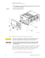
1. Place the analyzer bottom-side up on a flat surface.
2.
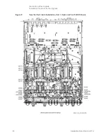
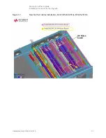
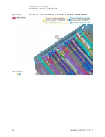
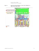
Remove the following cables in the order listed. Unless otherwise marked,
discard these cables; they will not be reused.
For Option 423 Only:
—
N5247-20027 Port 2 CPLR THRU to A45 port 2 bias tee
—
N5247-20080 A45 port 2 bias tee to A36 port 2 coupler
—
N5247-20029 A44 port 4 bias tee to A35 port 4 coupler
—
N5247-20021 Port 4 CPLR THRU to A44 port 4 bias tee
—
N5247-20022 A33 port 1 coupler to A42 port 1 bias tee
—
N5247-20010 Port 3 CPLR THRU to A43 port 3 bias tee
—
N5247-20081 Front-panel port 1 CPLR THRU to A42 port 1 bias tee
—
N5247-20028 A43 port 3 bias tee to A34 port 3 coupler
—
N5247-20058 A32 port 2 ref coupler to front-panel REF 2 SOURCE
OUT
For Option 425 Only:
—
N5247-20163 Port 2 CPLR THRU to A74 port 2 bias tee
—
N5247-20167 Front-panel port 1 CPLR THRU to A71 port 1 bias tee
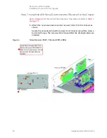
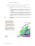
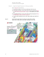
Step 6. Assemble the A23 Test Set Motherboard
For instructions, click the Chapter 7 bookmark “Removing and Replacing the
A23 Test Set Motherboard” in the PDF Service Guide
1
.
1. See


