18 Installation Note N5247-90116
Description of the Upgrade
Installation Procedure for the Upgrade
-
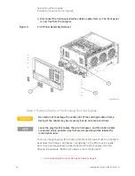
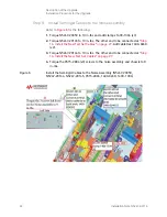
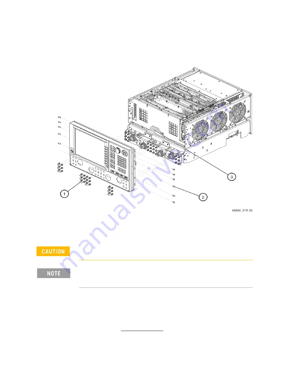
4. Disconnect the front panel interface ribbon cable (item
③
). The front panel
is now free from the analyzer.
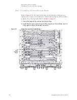
Figure 3
Front Panel Assembly Removal
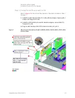
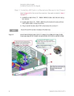
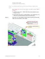
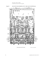
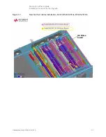
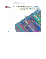
Step 5. Remove Some of the Existing Test Set Cables
To see an image showing the location of some of the cables click the Chapter 6
bookmark “Top Cables, All Cables - All Options” in the PDF Service Guide
1
.
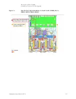
And, to see an image showing the location of the other cables, click the
Chapter 6 bookmark “Bottom RF Cables, 2-Port, Option 423”
.
Be careful not to damage the center pins of the semirigid cables. Some
flexing of the cables may be necessary but do not over-bend them.
Leave the gray flexible cables, the wire harnesses, and the ribbon cables
connected where possible. Any that are removed should be labeled for
reconnection later.
1. See


