


Keysight PXIe System and Cable Interface Installation Guide
31
M9022A, M9023A, M9024A System Module Installation
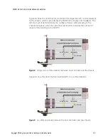
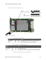
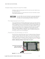
There are also a series of five LEDs across the top of the PC board and six LED
across the bottom of the PC board indicating power and configuration.
Figure 13
M9022A, M9023A, M9024A PC Board LEDs
D15
D14
D17
D9
D23
D13
D12
D11
D10
D32
D31
LED
Indicates
D17
PXI power is okay
D14
0.9 VDC power is okay
D15
1.8 VDC power is okay
D9
FPGA configuration is okay
D23
PCIe link status for FPGA
D10 - D13 PCIe Link Status when the backplane is 4-link routing. When the backplane is 2-link
routing, D10 indicates PCIe link status for left side mezzanine board.
D31- D32
PCIe Link Status when the backplane is 2-link routing. When the backplane is 4-link
routing, D31 indicates PCIe link status for left side mezzanine board.
Summary of Contents for M9021A
Page 2: ......
Page 6: ...vi ...
Page 44: ...44 Keysight PXIe System and Cable Interface Installation Guide Troubleshooting and Service ...
Page 45: ......


