background image

Notice

The

information

contained

in

this

document

is

subject

to

change

without

notice

.

This

document

contains

proprietary

information

which

is

protected

by

copyright.

All

rights

are

reserved.

No

part

of

this

document

may

be

photocopied,

reproduced,

or

translated

to

another

language

without

the

prior

written

consent

of

the

Agilent

T

echnologies

.

Agilent

T

echnologies

Japan,

Ltd.

Component

T

est

PGU-Kobe

1-3-2,

Murotani,

Nishi-ku,

Kobe-shi,

Hyogo

,

651-2241

Japan

W

arranty

This

Agilent

T

echnologies

instrument

product

is

warranted

against

defects

in

material

and

workmanship

for

a

period

of

one

year

from

the

date

of

shipment,

except

that

in

the

case

of

certain

components

listed

in

this

manual,

the

warranty

shall

be

for

the

specied

period.

During

the

warranty

period,

Agilent

T

echnologies

will,

at

its

option,

either

repair

or

replace

products

which

prove

to

be

defective

.

F

or

warranty

service

or

repair

,

this

product

must

be

returned

to

a

service

facility

designed

by

Agilent

T

echnologies

.

The

Buyer

shall

prepay

shipping

charges

to

Agilent

T

echnologies

and

Agilent

T

echnologies

shall

pay

shipping

charges

to

return

the

product

to

the

Buyer

.

However

,

the

Buyer

shall

pay

all

shipping

charges

,

duties

,

and

taxes

for

products

returned

to

Agilent

T

echnologies

from

another

country

.

Agilent

T

echnologies

warrants

that

its

software

and

rmware

designed

by

Agilent

T

echnologies

for

use

with

an

instrument

will

execute

its

programming

instruction

when

property

installed

on

that

instrument.

Agilent

T

echnologies

does

not

warrant

that

the

operation

of

the

instrument,

or

software

,

or

rmware

will

be

uninterrupted

or

error

free

.

Limitation

of

W

arranty

The

foregoing

warranty

shall

not

apply

to

defects

resulting

from

improper

or

inadequate

maintenance

by

the

Buyer

,

Buyer-supplied

software

or

interfacing,

unauthorized

modication

or

misuse

,

operation

outside

of

the

environmental

specications

for

the

product,

or

improper

site

preparation

or

maintenance

.

No

other

warranty

is

expressed

or

implied.

A

gilent

T

echnologies

specically

disclaims

the

implied

warranties

of

merchantability

and

tness

for

a

particular

purpose

.

Certication

The

Agilent

T

echnologies

certies

that

this

product

met

its

published

specications

at

the

time

of

shipment

from

the

factory

.

Agilent

T

echnologies

further

certies

that

its

calibration

measurements

are

traceable

to

the

United

States

National

Institute

of

Standards

and

T

echnology

,

to

the

extent

allowed

by

the

Institute's

calibration

facility

,

or

to

the

calibration

facilities

of

other

International

Standards

Organization

members

.

Summary of Contents for 16117C

Page 1: ...Keysight 16117C Low Noise Test Lead Operation and Service Manual...

Page 2: ......

Page 3: ......

Page 4: ...ing charges duties and taxes for products returned to Agilent Technologies from another country Agilent Technologies warrants that its software and rmware designed by Agilent Technologies for use with...

Page 5: ...mages whether based on contract tort or any other legal theory Assistance Product maintenance agreements and other customer assistance agreements are available for Agilent Technologies products If you...

Page 6: ...ns and updates which are incorporated at reprint do not cause the date to change The manual part number changes when extensive technical changes are incorporated December 1991 First Edition February 1...

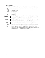
Page 7: ...placement and internal adjustments must be made only by quali ed maintenance personnel Do not replace components with the power cable connected Under certain conditions dangerous voltages may exist ev...

Page 8: ...ion sign denotes a hazard It calls attention to a procedure practice condition or the like which if not correctly performed or adhered to could result in damage to or destruction of part or all of the...

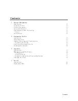
Page 9: ...Use Introduction 2 1 Initial Inspection 2 1 Ambient Environmental Considerations 2 3 Operating and Storage 2 3 Connecting the Adapter for Use 2 3 Packaging the Adapter 2 4 3 Operation Introduction 3 1...

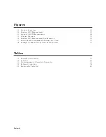
Page 10: ...1 3 2 Floating DUT Measurement Con guration 3 2 3 3 Interlock cable Assignment Wiring Side View 3 3 3 4 Example Con guration of Custom Test Fixture 3 5 Tables 1 1 Furnished Accessories 1 1 2 1 Content...

Page 11: ...the 16117C turn to Chapter 3 To order replaceable parts for the 16117C turn to Replaceable Parts in Chapter 4 Product Description The 16117C has been designed to operate speci cally with the 4339B Hig...

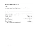
Page 12: ...ts against which the 16117C is tested When shipped from the factory the 16117C meets the speci cations listed in this section Applicable Test Voltage 1000 V maximum Applicable Test Current1 10 mA maxi...

Page 13: ...hould be in perfect electrical condition Verify this by carefully performing an incoming inspection to check the adapter for signs of physical damage and missing contents If any discrepancy is found n...

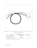
Page 14: ...ilent Part Number Quantity 1 Low Noise Test Lead 16117C 1 2 BNC Female Connector 1250 2317 1 3 Triaxial Female Connector 1250 2228 1 4 Operation and Service Manual1 16117 90041 1 1 Operation and Servi...

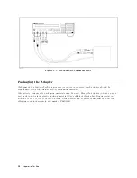
Page 15: ...9B connection with 16117C has two con gurations oating and grounded DUT measurement con gurations The connections are di erent for each con guration The connections are as shown in Figure 2 2 and Figu...

Page 16: ...ginal factory packaging materials Alteratively comparable packaging materials may be used Wrap the adapter in heavy paper and pack in anti static plastic packing material Use su cient shock absorbing...

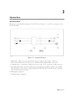
Page 17: ...h voltage BNC connector and is not compatible with standard BNC connectors 2 Triaxial cable The measured signal is carried on the center conductor of this connector 3 Interlock cable This connector en...

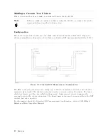
Page 18: ...with the 16117C Figure 3 2 Floating DUT Measurement Con guration The BNC connector provides source voltage up to 1000 V A triaxial connector is used for the measured signal path The triaxial connector...

Page 19: ...erlock cable has six lines The 4339B changes some settings Voltage Output Current Limit and Resistivity Mode depending on the interlock status Table 3 1 describes the role of each line Table 3 1 Pin A...

Page 20: ...Limitation GND GND Open 16008B No Limitation GND Open GND 16117B Current Limit 0 5 mA GND Open Open 04339 65005 100 V maximum Current Limit 1 mA Open GND GND Not Applicable n a Not Used No Voltage out...

Page 21: ...lose of this cover Figure 3 4 Example Con guration of Custom Test Fixture Center conductor of BNC connector and center conductor of triaxial connector is connected to contact of DUT A source voltage o...

Page 22: ...d that operator can measure safely To keep safety condition you must execute following checking procedure periodically This procedure assumes your xture has top cover interlocing source voltage output...

Page 23: ...Holder with Nuts 1 16117 87103 2 Warning Label Red on BNC and Triaxial cable 16117 87104 1 Label Yellow on Interlock cable 16117 61604 1 Cable Assembly Triaxial 2 16117 61605 1 Cable Assembly BNC 2 1...

Page 24: ......

Page 25: ...This information is subject to change without notice Keysight Technologies 2014 Edition 6 November 2014 16117 90041 16117 90041 www keysight com...

Reviews: