background image

141

www.keyestudio.com

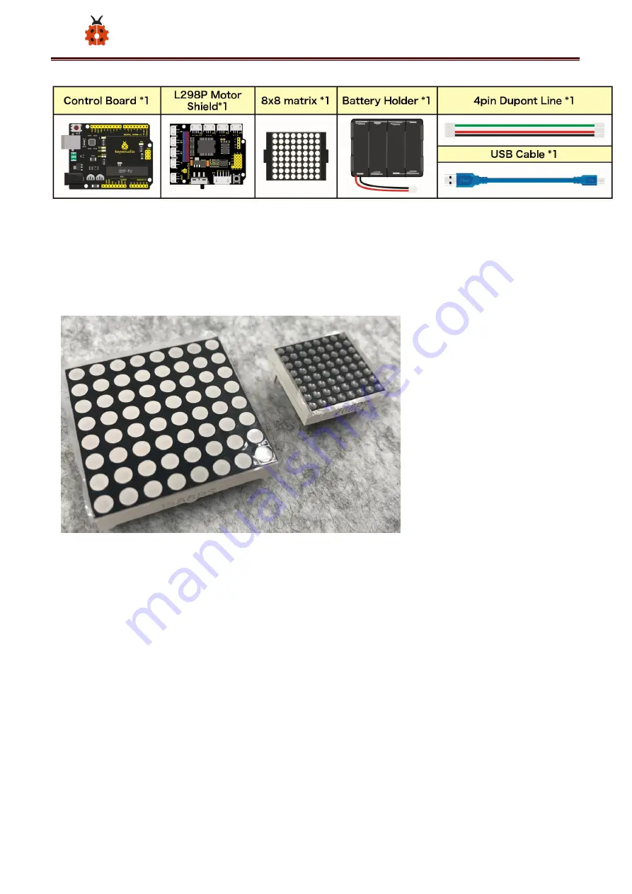
(3) 8*8 Dot Matrix

Composed of LED

emitting tube diodes,

LED dot matrix are

applied widely to public

information display like

advertisement screen and bulletin board, by controlling LED to show words,

pictures and videos, etc.

Divided into single-color, double-color, and three-color lights according to

emitting color , LED dot matrix could show red, yellow, green and even true

color.

There are 4×4, 8×8 and 16×16 different types matrix.

Summary of Contents for Smart Little Turtle Robot V3

Page 1: ...vice 3 Warning 4 Copyright 4 1 Introduction 5 2 Features 7 3 Specification 7 4 Product Kit 8 5 Assembly Guide 13 Step 1 Bottom Motor Wheel 13 Step 2 Assemble Parts 15 Step 3 Install Top PCB 20 Step 4...

Page 2: ...Project 2 Adjust LED Brightness 67 Project 3 Line Tracking Sensor 75 Project 4 Servo Control 83 Project 5 Ultrasonic Sensor 92 Project 6 IR Reception 104 Project 7 Bluetooth Remote Control 113 Project...

Page 3: ...rn Arduino knowledge All of our products comply with international quality standards and are greatly appreciated in a variety of different markets throughout the world Welcome check more contents from...

Page 4: ...this tutorial Improper operation may cause overheating and damage parts Do not touch and immediately disconnect the circuit power Copyright The keyestudio trademark and logo are the copyright of KEYES...

Page 5: ...5 www keyestudio com 1 Introduction...

Page 6: ...rn it into an output activating a motor turning on an LED publishing something online Based on this Keyestudio team has designed a turtle robot It has a processor which is programmable using the Ardui...

Page 7: ...ly easily 3 High Tenacity Aluminum alloy bracket metal motors high quality wheels and tracks 4 High extension expand other sensors and modules through motor driver shield and sensor shield 5 Multiple...

Page 8: ...mode dual H bridge drive Ultrasonic induction angle 15 degrees Ultrasonic detection distance 2cm 400cm Infrared remote control distance 10M measured Bluetooth remote control distance 50M measured Blue...

Page 9: ...ompatible 1 2 Keyestudio Quick Connectors Motor Driver Shield 1 3 Keyestudio Quick Connectors IR Receiver 1 4 Keyestudio Quick Connectors Line Tracking Sensor 1 5 Keyestudio Quick Connectors 12FN20 Mo...

Page 10: ...eyestudio Bluetooth Module HC 06 1 10 Keyestudio JMFP 4 17 86 40 6 5MM Remote Control without batteries 1 11 Double head JST PH2 0MM 5P 24AWG Blue green yellow red black Wire 15CM 1 12 Double head JST...

Page 11: ...Battery Holder with JST PH2 0MM 2P Lead 1 16 4 Slot AA Battery Holder 1 17 M2 12MM Round Head Screws 4 18 M2 Nickel Plated Nuts 4 19 M3 6MM Round Head Screws 27 20 M3 6MM Flat Head Screws 2 21 M3 Nick...

Page 12: ...e Mount 2 27 Black Plastic Platform 1 28 3PI MiniQ Universal Caster 304 Stainless Steel 2 29 Black yellow Handle 3 40MM Cross Screwdriver 1 30 1m Transparent Blue USB Cable 1 31 Black 3 100MM Ties 5 3...

Page 13: ...pont Cable 1 36 Keyestudio Red LED Module 1 37 Decorative Board 5 Assembly Guide Note Peel the plastic film off the board first when installing the smart car To be honest we never intend to send wood...

Page 14: ...14 www keyestudio com M3 6MM Flat Head Screw 2 M3 Nickel Plated Nut 2 Bottom PCB 1 Tracking Sensor 1 Universal Caster 2...

Page 15: ...emble Parts Prepare the parts as follows M3 6MM Round Head Screw 2 M2 Nut 4 12FN20 Motor 2 U type Holder 2 N20 Motor Wheel 2 2P Wire 2 5P Wire 1 M2 12MM Round Head Screw 4 2 cell AA Battery Holder 1 M...

Page 16: ...16 www keyestudio com...

Page 17: ...17 www keyestudio com...

Page 18: ...18 www keyestudio com...

Page 19: ...19 www keyestudio com...

Page 20: ...20 www keyestudio com Step 3 Install Top PCB Prepare the parts as follows Top PCB 1 M3 Nut 1 M3 6MM Round Head Screw 9 M3 10MM Hexagon Copper Bush 8 IR Receiver Sensor 1...

Page 21: ...21 www keyestudio com Step 4 Mount Control Board Prepare the parts as follows V4 0 Board 1 Motor Drive Shield V2 1 M3 6MM Round Head Screw 4...

Page 22: ...22 www keyestudio com...

Page 23: ...3 www keyestudio com Step 5 Servo Plastic Platform Prepare the parts as follows Servo 1 M2 4 Screw 1 Black Tie 2 Ultrasonic Sensor 1 Black Plastic Platform 1 M1 2 4 Tapping Screw 4 M2 8 Tapping Screw...

Page 24: ...24 www keyestudio com...

Page 25: ...25 www keyestudio com...

Page 26: ...26 www keyestudio com...

Page 27: ...27 www keyestudio com Step 6 Final Assembly Prepare the parts as follows M3 6MM Round Head Screw 12 M3 40MM Hexagon Copper Bush 4 8x8 Dot Matrix 1 Jumper Wire 4...

Page 28: ...28 www keyestudio com...

Page 29: ...29 www keyestudio com...

Page 30: ...30 www keyestudio com...

Page 31: ...31 www keyestudio com Step 7 Hook up Guide...

Page 32: ...32 www keyestudio com...

Page 33: ...33 www keyestudio com...

Page 34: ...wnload Arduino IDE from the official website https www arduino cc click the SOFTWARE on the browse bar click DOWNLOADS to enter download page as shown below There are various versions Of IDE for Ardui...

Page 35: ...e Zip packages We suggest you use the first one that installs directly everything you need to use the Arduino Software IDE including the drivers With the Zip package you need to install the drivers ma...

Page 36: ...lopment Board We need to know keyestudio V4 0 development board as a core of this smart car Keyestudio V4 0 development board is an Arduino uno compatible board which is based on ATmega328P MCU and wi...

Page 37: ...37 www keyestudio com It has 14 digital input output pins of which 6 can be used as PWM output s 6 analog inputs a 16 MHz quartz crystal a USB connection a power jack 2 ICSP headers and a reset button...

Page 38: ...t the microcontroller simply conn ect it to a computer with a USB cable or power it via an external DC power jack DC 7 12V or via female headers Vin GND DC 7 12V to get started Microcontroller ATmega3...

Page 39: ...B used by bootloader SRAM 2 KB ATmega328P PU EEPROM 1 KB ATmega328P PU Clock Speed 16 MHz LED_BUILTIN D13 2 Installing V4 0 board Driver Let s install the driver of keyestudio V4 0 board The USB TTL c...

Page 40: ...intend to install manually open the device manager of computer Right click Computer Properties Device Manager There is a yellow exclamation mark on the page which implies installing unsuccessfully Th...

Page 41: ...41 www keyestudio com Click OK to enter the following page click browse my computer for updated driver software find out the installed or downloaded ARDUINO software As shown below...

Page 42: ...iver folder and you can see the driver of CP210X series chips We click Browse then find out the driver folder or you could enter driver to search in rectangular box then click next the driver will be...

Page 43: ...43 www keyestudio com Open device manager we will find the yellow exclamation mark disappear The driver of CP2102 is installed successfully...

Page 44: ...44 www keyestudio com...

Page 45: ...visions of driver If your development board is Arduino board install the driver as follows Step 1 Plug in the development board click Computer Properties Device Manager you could see the unknown devi...

Page 46: ...46 www keyestudio com Step 3 click browse my computer for updated driver software Step 4 find out the folder where the ARDUINO software is installed click drivers folder and tap Next...

Page 47: ...47 www keyestudio com Step 5 the driver is installed successfully The device manager shows the serial port of Arduino...

Page 48: ...48 www keyestudio com 4 Arduino IDE Setting Click icon open Arduino IDE...

Page 49: ...ors when uploading the program to the board you need to select the correct Arduino board that matches the board connected to your computer Then come back to the Arduino software you should click Tools...

Page 50: ...50 www keyestudio com Then select the correct COM port you can see the corresponding COM port after the driver is successfully installed...

Page 51: ...51 www keyestudio com Before uploading the program to the board let s demonstrate the function of each symbol in the Arduino IDE toolbar...

Page 52: ...etch to your Arduino board C Used to create shortcut window of a new sketch D Used to directly open an example sketch E Used to save the sketch F Used to send the serial data received from board to th...

Page 53: ...53 www keyestudio com Set board and COM port the corresponding board and COM port are...

Page 54: ...54 www keyestudio com shown on the lower right of IDE Click to start compiling the program check errors...

Page 55: ...55 www keyestudio com Click to upload the program upload successfully...

Page 56: ...ish the first program 7 Add project Libraries 1 What are Libraries Libraries are a collection of code that makes it easy for you to connect to a sensor display module etc For example the built in Liqu...

Page 57: ...to Install a Library Here we will introduce the most simple way for you to add libraries Step 1 After downloading well the Arduino IDE you can right click the icon of Arduino IDE Find the option Open...

Page 58: ...keyestudio com Step 3 Next to find out the libraries folders of turtle robot seen in the link https fs keyestudio com KS0464 you just need to replicate and paste it into the libraries folder of Ardui...

Page 59: ...59 www keyestudio com...

Page 60: ...60 www keyestudio com Then the libraries of turtle robot are installed successfully as shown below...

Page 61: ...61 www keyestudio com 7 Projects The whole project begins with basic program Starting from simple to...

Page 62: ...sensor shield or control board V is positive pole and linked with V VCC or 5V on the sensor shield or control board Project 1 LED Blink 1 Description For the starter and enthusiast this is a fundamen...

Page 63: ...63 www keyestudio com Control interface digital port Working voltage DC 3 3 5V Pin spacing 2 54mm LED display color red 3 Components 3 Wiring Diagram...

Page 64: ...on development board and S pins of LED module are respectively connected to G 5V and D3 pins of shield 4 Test Code keyestudio smart turtle robot lesson 1 1 Blink http www keyestudio com void setup pi...

Page 65: ...gitalWrite 3 LOW turn the LED off by making the voltage LOW delay 1000 wait for a second 5 Test Result Upload the program LED connected to D3 flickers with the interval of 1s 6 Code Explanation pinMod...

Page 66: ...n 1 2 delay http www keyestudio com void setup initialize digital pin 11 as an output pinMode 3 OUTPUT the loop function runs over and over again forever void loop digitalWrite 3 HIGH turn the LED on...

Page 67: ...you can change the step length and delay time in the code so as to demonstrate different breathing effect PWM is a means of controlling the analog output via digital means Digital control is used to g...

Page 68: ...d If output five hundred 1 that is 5V if all of which is 1 that is 0V If output 010101010101 in this way then the output port is 2 5V which is like showing movie The movie we watch are not completely...

Page 69: ...69 www keyestudio com 3 Hook up Diagram 4 Test Code keyestudio smart turtle robot lesson 2 1 pwm http www keyestudio com...

Page 70: ...Mode ledPin OUTPUT initialize ledpin as an output void loop for value 0 value 255 value value 1 analogWrite ledPin value LED lights gradually light up delay 5 delay 5MS for value 255 value 0 value val...

Page 71: ...tely 6 Code Explanation When we need to repeat some statements we could use FOR statement FOR statement format is shown below FOR cyclic sequence Round 1 1 2 3 4 Round 2 2 3 4 Until number 2 is not es...

Page 72: ...write an analog value from 0 255 for PWM port so the value is in the range of 0 255 Attention that you only write the digital pins with PWM function such as pin 3 5 6 9 10 11 PWM is a technology to ob...

Page 73: ...p to bottom the duty cycle of first square wave is 0 and its corresponding value is 0 The LED brightness is lowest that is turn off The more time high level lasts the brighter the LED Therefore the la...

Page 74: ...eyestudio smart turtle robot lesson 2 2 pwm http www keyestudio com int ledPin 3 Define the LED pin at D3 void setup pinMode ledPin OUTPUT initialize ledpin as an output void loop for int value 0 valu...

Page 75: ...sed here is the TCRT5000 infrared tube Its working principle is to use the different reflectivity of infrared light to the color then convert the strength of the reflected signal into a current signal...

Page 76: ...ivity of the sensor 2 Specification Operating Voltage 3 3 5V DC Interface 5PIN Output Signal Digital signal Detection Height 0 3 cm Special note before testing turn the potentiometer on the sensor to...

Page 77: ...77 www keyestudio com 4 Connection Diagram 5 Test Code keyestudio smart turtle robot lesson 3 1...

Page 78: ...l_L val_R val_M define the variable value of three sensors void setup Serial begin 9600 initialize serial communication at 9600 bits per second pinMode L_pin INPUT make the L_pin as an input pinMode M...

Page 79: ...rint right Serial println val_R delay 500 delay in between reads for stability 6 Test Result Upload the code on development board open serial monitor to check line tracking sensors And the displayed v...

Page 80: ...7 Code Explanation Serial begin 9600 Initialize serial port set baud rate to 9600 pinMode Define the pin as input or output mode digitalRead Read the state of pin which are generally HIGH and LOW leve...

Page 81: ...We could control LED by line tracking sensor Test Code keyestudio smart turtle robot lesson 3 2 Line Track sensor http www keyestudio com int L_pin 6 pins of left line tracking sensor int M_pin 7 pins...

Page 82: ...e L_pin INPUT make the L_pin as an input pinMode M_pin INPUT make the M_pin as an input pinMode R_pin INPUT make the R_pin as an input pinMode 3 OUTPUT void loop val_L digitalRead L_pin read the L_pin...

Page 83: ...line tracking sensor detects signals Serial println HIGH digitalWrite 3 HIGH LED is off else if left line tracking sensor doesn t detect signals Serial println LOW digitalWrite 3 LOW LED is off Uploa...

Page 84: ...s the acquired DC bias voltage to the voltage of the potentiometer and obtain the voltage difference output When the motor speed is constant the potentiometer is driven to rotate through the cascade r...

Page 85: ...between 0 5ms 2 5ms The width corresponds the rotation angle from 0 to 180 But note that for different brand motor the same signal may have different rotation angle The corresponding servo angles are...

Page 86: ...2500 sec No load speed 0 12 0 01 sec 60 DC 4 8V 0 1 0 01 sec 60 DC 6V No load current 200 20mA DC 4 8V 220 20mA DC 6V Stopping torque 1 3 0 01kg cm DC 4 8V 1 5 0 1kg cm DC 6V Stop current 850mA DC 4...

Page 87: ...is attached to digital 10 The servo has to be connected to external power due to its high demand for driving servo current Generally the current of development board is not enough If without connecte...

Page 88: ...of servo to output procedure 0 set the angle of servo to 0 degree void loop for pos 0 pos 180 pos 1 goes from 0 degrees to 180 degrees in steps of 1 degree procedure pos tell servo to go to position...

Page 89: ...lsewidth The duration of high level is pulse width digitalWrite servoPin LOW delay 20 pulsewidth 1000 the cycle is 20ms the low level last for the rest of time Upload code successfully servo swings ba...

Page 90: ...ng code 6 Test Code2 keyestudio smart turtle robot lesson 4 2 servo http www keyestudio com include Servo h Servo myservo create servo object to control a servo twelve servo objects can be created on...

Page 91: ...rees to 180 degrees in steps of 1 degree myservo write pos tell servo to go to position in variable pos delay 15 waits 15ms for the servo to reach the position for pos 180 pos 0 pos 1 goes from 180 de...

Page 92: ...erface Set servo interface port 9 and 10 are available 2 write angle The statement to set rotation angle of servo the angle range is from 0 to 180 3 read The statement to read angle of servo read the...

Page 93: ...ing used in a wide range of electronics projects for creating obstacle detection and distance measuring application as well as various other applications Here we have brought the simple method to meas...

Page 94: ...onic waves encounter the object and are reflected back the module outputs an echo signal so it can determine the distance of object from the time difference between trigger signal and echo signal The...

Page 95: ...and detect whether there is a signal return This step will be completed automatically by the module 3 If the signal returns the Echo pin will output a high level and the duration of the high level is...

Page 96: ...96 www keyestudio com 5 Connection Diagram...

Page 97: ...eld VCC 5v V Trig 12 S Echo 13 S Gnd Gnd G 6 Test Code keyestudio smart turtle robot lesson 5 1 Ultrasonic sensor http www keyestudio com int trigPin 12 Trigger int echoPin 13 Echo long duration cm in...

Page 98: ...alWrite trigPin HIGH delayMicroseconds 10 digitalWrite trigPin LOW Read the signal from the sensor a HIGH pulse whose duration is the time in microseconds from the sending of the ping to the reception...

Page 99: ...elay 250 7 Test Result Upload test code on the development board open serial monitor and set baud rate to 9600 The detected distance will be displayed the unit is cm and inch Hinder the ultrasonic sen...

Page 100: ...distance traveltime 2 x speed of sound The speed of sound is 343m s 0 0343 cm uS 1 29 1 cm uS Or in inches 13503 9in s 0 0135in uS 1 74in uS We need to divide the traveltime by 2 because we have to t...

Page 101: ...smart turtle robot lesson 5 2 Ultrasonic LED http www keyestudio com int trigPin 12 Trigger int echoPin 13 Echo long duration cm inches void setup Serial begin 9600 Serial Port begin pinMode trigPin...

Page 102: ...gPin HIGH delayMicroseconds 10 digitalWrite trigPin LOW Read the signal from the sensor a HIGH pulse whose duration is the time in microseconds from the sending of the ping to the reception of its ech...

Page 103: ...print cm Serial println delay 250 if cm 2 cm 10 Serial println HIGH digitalWrite 3 HIGH else Serial println LOW digitalWrite 3 LOW Upload test code to development board and block ultrasonic sensor by...

Page 104: ...an infrared remote control and infrared receiving module and a single chip microcomputer capable of decoding The 38K infrared carrier signal emitted by remote controller is encoded by the encoding chi...

Page 105: ...e use is an infrared receiver module Mainly composed of an infrared receiver head it is a device that integrates reception amplification and demodulation Its internal IC has completed demodulation and...

Page 106: ...106 www keyestudio com Operating Voltage 3 3 5V DC Interface 3PIN Output Signal Digital signal Receiving Angle 90 degrees Frequency 38khz Receiving Distance 10m 3 Components 4 Connection Diagram...

Page 107: ...studio development board Attention On the condition that digital ports are not available analog ports can be regarded as digital ports A0 equals to D14 A1 is equivalent to digital 15 Import the librar...

Page 108: ...CV_PIN decode_results results decode results exist in the result of decode results void setup Serial begin 9600 irrecv enableIRIn Enable receiver void loop if irrecv decode results decode successfully...

Page 109: ...monitor and set baud rate to 9600 point remote control to IR receiver and the corresponding value will be shown if pressing so long the error codes will appear Below we have listed out each button val...

Page 110: ...continuously to make ure if decoding successfully irrecv decode results after decoding successfully this function will come back to true and keep result in results After decoding a IR signals run the...

Page 111: ...ED to D3 then press the keys of remote control to make LED light up and off keyestudio smart turtle robot lesson 6 2 IRremote http www keyestudio com include IRremote h int RECV_PIN A1 define the pin...

Page 112: ...t pin 4 of LED to OUTPUT void loop if irrecv decode results if results value 0xFF02FD a 0 according to the above key value press OK on remote control LED will be controlled Serial println HIGH digital...

Page 113: ...ff Project 7 Bluetooth Remote Control 1 Description Bluetooth a simple wireless communication module most popular since the last few decades and easy to use are being used in most of the battery power...

Page 114: ...ed for establishing wireless data communication The module is designed by using the Texas Instruments CC2540 or CC2541 Bluetooth low energy BLE System on Chip SoC 2 Specification Bluetooth protocol Bl...

Page 115: ...nsumption Auto sleep mode stand by current 400uA 800uA 8 5mA during transmission Power supply 5V DC Working temperature 5 to 65 Centigrade 3 Components 3 Connection Diagram 1 STATE state test pins con...

Page 116: ...ally keep it unconnected Pay attention to the pin direction when inserting Bluetooth module and don t insert it before uploading test code 4 Test Code keyestudio smart turtle robot lesson 7 1 bluetoot...

Page 117: ...read Read data from serial buffer Serial println ble_val Print There will be contradiction between serial communication of code and communication of Bluetooth when uploading code therefore don t link...

Page 118: ...signal In this project we send signal to control robot car via cellphone Then we need to download the APP 1 iOS system Note Allow APP to access location in settings of your cellphone when connecting...

Page 119: ...LE Scanner and download Enable location in settings of your cellphone otherwise app may not be searched 3 After installation open App and enable Location and Bluetooth permission 4 Open App the name o...

Page 120: ...120 www keyestudio com 5 After connecting to HMSoft click it to get multiple options such as device information access permission general and custom service Choose CUSTOM SERVICE...

Page 121: ...121 www keyestudio com 6 Then pop up the following page...

Page 122: ...122 www keyestudio com 7 Click Read Notify WriteWithoutResponse to enter the following page...

Page 123: ...123 www keyestudio com 8 Click Write Value to enter HEX or Text 9 Open the serial monitor on Arduino enter 0 or other characters on Text interface...

Page 124: ...124 www keyestudio com 10 Then click Write and open serial monitor to view if there is a 0 signal...

Page 125: ...al available 0 it means that serial receives the data and can be read Serial read Read a data of a Byte in buffer of serial port for instance device sends data to Arduino via serial port then we could...

Page 126: ...uetooth http www keyestudio com int ledpin 3 void setup Serial begin 9600 pinMode ledpin OUTPUT void loop int i if Serial available i Serial read Serial println DATA RECEIVED if i 1 digitalWrite ledpi...

Page 127: ...keyestudio com if i 0 digitalWrite ledpin 0 Serial println led off Click Write on APP when you enter 1 LED will be on when you input 0 LED will be off Remember to remove the Bluetooth module after fi...

Page 128: ...298P solution L298P is an excellent high power motor driver IC produced by STMicroelectronics It can directly drive DC motors two phase and four phase stepping motors The driving current up to 2A and...

Page 129: ...129 www keyestudio com...

Page 130: ...dissipation 25W T 75 6 Working temperature 25 130 7 Control signal input level high level 2 3V Vin 5V low level 0 3V Vin 1 5V 3 Drive Robot to Move Through the above diagram the direction pin of B mot...

Page 131: ...LOW 200 Rotate clockwise Go back HIGH 200 Rotate anticlockwise HIGH 200 Rotate anticlockwise Rotate anticlockwise HIGH 200 Rotate anticlockwise LOW 200 Rotate clockwise Rotate clockwise LOW 200 Rotat...

Page 132: ...motor driver shield http www keyestudio com define ML_Ctrl 2 define the direction control pin of A motor define ML_PWM 9 define the PWM control pin of A motor define MR_Ctrl 4 define the direction co...

Page 133: ...rection control pin of B motor to output pinMode MR_PWM OUTPUT set PWM control pin of B motor to output void loop front digitalWrite ML_Ctrl LOW set the direction control pin of A motor to LOW analogW...

Page 134: ...trol pin of B motor to HIGH level analogWrite MR_PWM 200 set the PWM control speed of B motor to 200 delay 2000 delay in 2000ms left digitalWrite ML_Ctrl HIGH set the direction control pin of A motor...

Page 135: ...tor to HIGH level analogWrite MR_PWM 200 set the PWM control speed of B motor to 200 delay 2000 delay in 2000ms stop analogWrite ML_PWM 0 set the PWM control speed of A motor to 0 analogWrite MR_PWM 0...

Page 136: ...of motor is regulated by PWM and the pins that decide the speed of motor must be PWM pins 8 Extension Practice Adjust the speed that PWM controls the motor hook up in same way keyestudio smart turtle...

Page 137: ...de MR_Ctrl OUTPUT set the direction control pin of B motor to OUTPUT pinMode MR_PWM OUTPUT set the PWM control pin of B motor to OUTPUT void loop digitalWrite ML_Ctrl LOW set the direction control pin...

Page 138: ...he direction control pin of B motor to high level analogWrite MR_PWM 100 set the PWM control speed of B motor to 100 back delay 2000 delay in 2000ms digitalWrite ML_Ctrl HIGH set the direction control...

Page 139: ...WM control speed of A motor to 100 digitalWrite MR_Ctrl HIGH set the direction control pin of B motor to HIGH level analogWrite MR_PWM 100 set the PWM control speed of B motor to 100 right delay 2000...

Page 140: ...multiplexed to control 64 LEDs you need 16 pins That s a lot of pins and there are driver chips like the MAX7219 that can control a matrix for you but there s a lot of wiring to set up and they take...

Page 141: ...formation display like advertisement screen and bulletin board by controlling LED to show words pictures and videos etc Divided into single color double color and three color lights according to emitt...

Page 142: ...low Every LED is installed on the cross point of row line and column line When the voltage on some line increases and the voltage on some column line is reduced the LED on the cross point will light u...

Page 143: ...143 www keyestudio com The definition inner pins are shown below...

Page 144: ...the voltage of pin 13 4 HT16K33 8X8 Dot Matrix The HT16K33 is a memory mapping and multi purpose LED controller driver The max Display segment numbers in the device is 128 patterns 16 segments and 8 c...

Page 145: ...line bidirectional I2C bus The working schematic of HT16K33 chip We design the drive module of 8 8 dot matrix based on the above principle We could control the dot matrix by I2C communication and two...

Page 146: ...Introduction for Modulus Tool The online version of dot matrix modulus tool http dotmatrixtool com Open links to enter the following page The dot matrix is 8 8 in this project so set the height to 8 w...

Page 147: ...er to select Row major Generate hexadecimal data from the pattern As shown below press the left mouse button to select the right button to cancel draw the pattern you want click Generate and the hexad...

Page 148: ...xadecimal code 0x00 0x66 0x00 0x00 0x18 0x42 0x3c 0x00 is what we display and save it 6 Connection Diagram Note The pin G V SDA and SCL of dot matrix module are separately connected to G 5V A4 and A5...

Page 149: ...udio com include Matrix h Matrix myMatrix A4 A5 set pins to communication pins define an array uint8_t LedArray1 8 0x00 0x66 0x00 0x00 0x18 0x42 0x3c 0x00 uint8_t LEDArray 8 define an array by modulus...

Page 150: ...ray for int j 7 j 0 j Every data byte has 8 bit therefore loop for eight times if LEDArray i 0x01 0 judge if the last bit of data is greater than 0 myMatrix drawPixel j i 1 light up the corresponding...

Page 151: ...151 www keyestudio com myMatrix writeDisplay dot matrix shows 8 Test Result Upload code plug in power and turn on the switch of the robot car 8 8 dot matrix shows smile face pattern...

Page 152: ...sion Practice Let s make dot matrix draw a heart just enter the website and draw the following pattern http dotmatrixtool com Then we get the code of heart pattern Replace the above code of heart patt...

Page 153: ...tion pins define an array uint8_t LedArray1 8 0x66 0x99 0x81 0x81 0x42 0x24 0x18 0x00 uint8_t LEDArray 8 define an array by modulus tool without initial value void setup myMatrix begin 0x70 communicat...

Page 154: ...EDArray i 0x01 0 judge if the last bit of data is greater than 0 myMatrix drawPixel j i 1 light up the corresponding point else otherwise myMatrix drawPixel j i 0 turn off the corresponding point LEDA...

Page 155: ...155 www keyestudio com Upload code plug in power and turn on the switch of the robot car 8 8 dot matrix shows the heart pattern...

Page 156: ...ng Robot 1 Description The previous projects are inclusive of the knowledge of multiple sensors and modules Next we will work on a little challenging task We could make a line tracking car on top of t...

Page 157: ...ght tracking sensor detects black line HIGH detects white line LOW Condition 1 Status 2 detecting the left and the right tracking sensor Status Middle tracking sensor detects black line left tracking...

Page 158: ...t Set PWM to 200 Middle tracking sensor detects white line Only left line tracking sensor detects black line Rotate to left Set PWM to 200 Only right line tracking sensor detects black line Rotate to...

Page 159: ...159 www keyestudio com 3 Connection Diagram 4 Test Code...

Page 160: ...wm 5 define PWM control pin of B motor int sensor_l 6 define the pin of left line tracking sensor int sensor_c 7 define the pin of middle line tracking sensor int sensor_r 8 define the pin of right li...

Page 161: ...he pins of left line tracking sensor to INPUT pinMode sensor_c INPUT set the pins of middle line tracking sensor to INPUT pinMode sensor_r INPUT set the pins of right line tracking sensor to INPUT voi...

Page 162: ...f c_val 1 if the state of middle one is 1 which means detecting black line front car goes forward else if l_val 1 r_val 0 if only left line tracking sensor detects black trace left car turns left else...

Page 163: ...tatus of going forward digitalWrite left_ctrl LOW analogWrite left_pwm 200 digitalWrite right_ctrl LOW analogWrite right_pwm 200 void back define the state of going back digitalWrite left_ctrl HIGH an...

Page 164: ...wm 200 void right define the right turning state digitalWrite left_ctrl LOW analogWrite left_pwm 200 digitalWrite right_ctrl HIGH analogWrite right_pwm 200 void Stop define the state of stop analogWri...

Page 165: ...obot car Turtle car walks along black lines Project 11 Ultrasonic Follow Robot 1 Description In this project we detect the distance value of the obstacle to drive two motors so as to make robot car mo...

Page 166: ...stance of front obstacles distance unit cm Setting Set servo to 90 Make dot matrix show smile face pattern Condition Distance 8 Status Go back PWM set to 200 Condition distance 8 and distance 13 Statu...

Page 167: ...167 www keyestudio com 2 Hook up Diagram...

Page 168: ...smart turtle robot lesson 11 flowing turtle http www keyestudio com int left_ctrl 2 define the direction control pin of A motor int left_pwm 9 define the speed control pin of A motor int right_ctrl 4...

Page 169: ...4 sr04 SR04 ECHO_PIN TRIG_PIN long distance void setup Serial begin 9600 open serial monitor and set baud rate to 9600 pinMode left_ctrl OUTPUT set direction control pin of A motor to OUTPUT pinMode l...

Page 170: ...an 8 back go back else if distance 8 distance 13 if 8 distance 13 Stop stop else if distance 13 distance 35 if 13 distance 35 front follow else otherwise Stop stop void front define the status of goin...

Page 171: ...gWrite left_pwm 200 digitalWrite right_ctrl HIGH analogWrite right_pwm 200 void left define the status of turning left digitalWrite left_ctrl HIGH analogWrite left_pwm 200 digitalWrite right_ctrl LOW...

Page 172: ...p analogWrite left_pwm 0 analogWrite right_pwm 0 4 Test Result Upload the code to the development board and plug in power Adjust the servo on turtle robot car to 90 dot matrix will display smile face...

Page 173: ...ption We ve learned LED matrix motor drive ultrasonic sensor and servo in previous lessons Next we could make an ultrasonic avoiding robot The measured distance between ultrasonic sensor and obstacle...

Page 174: ...set servo to 180 a1 unit cm measured distance of right obstacle set servo to 0 a2 unit cm Setting set the initial angle of servo to 90 Dot matrix shows smile face pattern Condition1 Status a 10 Stop f...

Page 175: ...w keyestudio com PWM to 200 and go font set PWM to 200 a1 a2 Set the angle of servo to 90 rotate to right for 400ms set PWM to 200 and go front set PWM to 200 Condition 1 Status a 10 Go front set PWM...

Page 176: ...Test Code keyestudio smart turtle robot lesson 12 avoiding turtle http www keyestudio com include ks_Matrix h Matrix myMatrix A4 A5 set the pins of dot matrix to A4 and A5 Array used to store the dat...

Page 177: ...18 0x18 0x18 0x18 0x18 0x00 0x18 0x18 uint8_t LEDArray 8 const int left_ctrl 2 define direction control pin of A motor const int left_pwm 9 define PWM control pin of A motor const int right_ctrl 4 def...

Page 178: ...otor to OUTPUT pinMode left_pwm OUTPUT set PWM control pin of A motor to OUTPUT pinMode right_ctrl OUTPUT set direction control pin of B motor to OUTPUT pinMode right_pwm OUTPUT set PWM control pin of...

Page 179: ...an 0 and less than 10 car_Stop stop myMatrix clear myMatrix writeDisplay show stop pattern matrix_display matrix_stop2 show stop pattern delay 100 servopulse servopin 180 servo rotates to 180 delay 20...

Page 180: ...t turning pattern servopulse servopin 90 servo rotates to 90 degree delay 50 myMatrix clear myMatrix writeDisplay matrix_display matrix_front2 show forward pattern else if the right distance is greate...

Page 181: ...go forward myMatrix clear myMatrix writeDisplay matrix_display matrix_front2 show forward pattern void servopulse int servopin int myangle the running angle of servo for int i 0 i 20 i pulsewidth mya...

Page 182: ...ogWrite left_pwm 200 digitalWrite right_ctrl LOW analogWrite right_pwm 200 void car_back go back digitalWrite left_ctrl HIGH analogWrite left_pwm 200 digitalWrite right_ctrl HIGH analogWrite right_pwm...

Page 183: ...turns right digitalWrite left_ctrl LOW analogWrite left_pwm 200 digitalWrite right_ctrl HIGH analogWrite right_pwm 200 void car_Stop stop analogWrite left_pwm 0 analogWrite right_pwm 0 this function...

Page 184: ...DArray i 0x01 0 myMatrix drawPixel j i 1 LEDArray i LEDArray i 1 myMatrix writeDisplay 4 Test Result After uploading the code on the keyestudio V4 0 board wire according to connection diagram Turn on...

Page 185: ...iption In this project we will make IR remote control robot car Press the button on IR remote control to drive robot car to move and the corresponding state pattern is displayed on the 8 16 LED matrix...

Page 186: ...ED matrix shows front icon FFA857 Back PWM set to 200 8 8 LED matrix shows back icon FF22DD Rotate to left PWM set to 200 8 8 LED matrix shows leftward icon FFC23D Rotate to right PWM set to 200 8 8 L...

Page 187: ...187 www keyestudio com 8 8 LED matrix shows rightward icon Flow Chart 2 Hook up Diagram...

Page 188: ...188 www keyestudio com Note IR receiver is connected to P4 interface 3 Test Code keyestudio smart turtle robot lesson 13 remote control turtle http www keyestudio com include ks_Matrix h...

Page 189: ...ft2 8 0x48 0x24 0x12 0x09 0x09 0x12 0x24 0x48 uint8_t matrix_right2 8 0x12 0x24 0x48 0x90 0x90 0x48 0x24 0x12 uint8_t matrix_stop2 8 0x18 0x18 0x18 0x18 0x18 0x00 0x18 0x18 uint8_t LEDArray 8 const in...

Page 190: ...upt driver crashes on setup give a clue to the user what s going on Serial println Enabling IRin irrecv enableIRIn Start the receiver Serial println Enabled IRin myMatrix begin 112 myMatrix clear void...

Page 191: ...break case 0xFFA857 car_back myMatrix clear myMatrix writeDisplay matrix_display matrix_back2 break case 0xFF22DD car_left myMatrix clear myMatrix writeDisplay matrix_display matrix_left2 break case 0...

Page 192: ...Receive the next value void car_front define the state of going front digitalWrite left_ctrl LOW analogWrite left_pwm 200 digitalWrite right_ctrl LOW analogWrite right_pwm 200 void car_back define th...

Page 193: ...logWrite right_pwm 200 void car_right set the status of right turning digitalWrite left_ctrl HIGH analogWrite left_pwm 200 digitalWrite right_ctrl LOW analogWrite right_pwm 200 void car_Stop define th...

Page 194: ...8 i LEDArray i matrix_value i for int j 7 j 0 j if LEDArray i 0x01 0 myMatrix drawPixel j i 1 LEDArray i LEDArray i 1 myMatrix writeDisplay 4 Test Result Upload code and press buttons on IR remote con...

Page 195: ...uetooth Remote Control 1 Description We ve learned the basic knowledge of Bluetooth in this lesson we will make a Bluetooth remote smart car In the experiment we default the HM 10 Bluetooth module as...

Page 196: ...key value of App Special Note Before uploading the test code you need to remove the Bluetooth module otherwise the test code will fail to upload After the code is uploaded successful then reconnect th...

Page 197: ...197 www keyestudio com if Serial available 0 BLE_val Serial read Serial println BLE_val Upload code to V4 0 development board and connect to Bluetooth module as shown below...

Page 198: ...lash Next to download the App Special note RXD TXD GND and VCC of Bluetooth module are respectively connected to TX RX GND and VCC The STATE and BRK pins don t need to be connected The pin G V SDA and...

Page 199: ...199 www keyestudio com For iOS system Search keyes BT car in App store After installation enter its interface Click Connect to search and pair Bluetooth...

Page 200: ...200 www keyestudio com 5 Click to enter the main page of turtle smart car...

Page 201: ...oid System 1 Enter Google play store to search Turtle Car allow APP to access location you could enable location in settings of your cellphone 2 The app icon is shown below after installation 3 Click...

Page 202: ...m 4 After connecting Bluetooth plug in power and LED indicator of Bluetooth module will flicker Tap to search Bluetooth 4 Click connect below HMSoft then the Bluetooth will be connected and its LED in...

Page 203: ...www keyestudio com After connecting Bluetooth module and open serial monitor to set baud rate to 9600 Press the button of the Bluetooth APP and the corresponding characters are displayed as shown bel...

Page 204: ...e button robot turns left release to stop Click to send S Stop Press R Release S Press the button robot turns right release to stop Press B Release S Press the button robot goes back release to stop C...

Page 205: ...205 www keyestudio com Click to send X Start line tracking function click Stop to exit We have read the character of each key on mobile APP via serial port and know the key function Flow Chart...

Page 206: ...e robot lesson 14 2 Bluetooth Control turtle http www keyestudio com include ks_Matrix h Matrix myMatrix A4 A5 Array used to store the data of pattern can be calculated by yourself or obtained from th...

Page 207: ...x12 uint8_t matrix_stop2 8 0x18 0x18 0x18 0x18 0x18 0x00 0x18 0x18 uint8_t LEDArray 8 unsigned char data_line 0 unsigned char delay_count 0 const int left_ctrl 2 define direction control pin of A moto...

Page 208: ...f Serial available 0 BLE_val Serial read Serial println BLE_val switch BLE_val case F car_front myMatrix clear myMatrix writeDisplay matrix_display matrix_front2 break case B car_back myMatrix clear m...

Page 209: ...yMatrix clear myMatrix writeDisplay matrix_display matrix_left2 break case R car_right myMatrix clear myMatrix writeDisplay matrix_display matrix_right2 break case S car_Stop myMatrix clear myMatrix w...

Page 210: ...LOW analogWrite right_pwm 200 void car_back go backward digitalWrite left_ctrl HIGH analogWrite left_pwm 200 digitalWrite right_ctrl HIGH analogWrite right_pwm 200 void car_left turn left digitalWrit...

Page 211: ...te right_ctrl HIGH analogWrite right_pwm 200 void car_Stop stop analogWrite left_pwm 0 analogWrite right_pwm 0 the function that dot matrix shows patterns void matrix_display unsigned char matrix_valu...

Page 212: ...o development board insert Bluetooth module open App to connect Bluetooth Next press icons on App to control turtle robot car to move Special Note you need to remove the Bluetooth module before upload...

Page 213: ...dio com Project 15 Multi purpose Bluetooth Robot 1 Description In previous projects the robot car only performs single function however in this lesson we integrate all of function to control smart car...

Page 214: ...214 www keyestudio com control Here is a simple flow chart of multi purpose robot car as for your reference 2 Connection Diagram...

Page 215: ...m 3 Test Code keyestudio smart turtle robot lesson 15 Multifunctional turtle robot http www keyestudio com include ks_Matrix h Matrix myMatrix A4 A5 Array used to store the data of pattern can be calc...

Page 216: ...nt8_t matrix_left2 8 0x48 0x24 0x12 0x09 0x09 0x12 0x24 0x48 uint8_t matrix_right2 8 0x12 0x24 0x48 0x90 0x90 0x48 0x24 0x12 uint8_t matrix_stop2 8 0x18 0x18 0x18 0x18 0x18 0x00 0x18 0x18 uint8_t LEDA...

Page 217: ...Serial begin 9600 irrecv enableIRIn Start the receiver servopulse servopin 90 pinMode left_ctrl OUTPUT pinMode left_pwm OUTPUT pinMode right_ctrl OUTPUT pinMode right_pwm OUTPUT pinMode sensor_l INPU...

Page 218: ...ntln BLE_val switch BLE_val case F car_front myMatrix clear myMatrix writeDisplay matrix_display matrix_front2 break case B car_back myMatrix clear myMatrix writeDisplay matrix_display matrix_back2 br...

Page 219: ...right myMatrix clear myMatrix writeDisplay matrix_display matrix_right2 break case S car_Stop myMatrix clear myMatrix writeDisplay matrix_display matrix_stop2 break case X tracking break case Y follow...

Page 220: ...track_flag 0 while track_flag 0 distance1 sr04 Distance if distance1 10 distance1 0 car_Stop myMatrix clear myMatrix writeDisplay matrix_display matrix_stop2 delay 100 servopulse servopin 180 delay 10...

Page 221: ...nce2 distance3 car_left myMatrix clear myMatrix writeDisplay matrix_display matrix_left2 servopulse servopin 90 delay 100 else car_right myMatrix clear myMatrix writeDisplay matrix_display matrix_righ...

Page 222: ...m car_front myMatrix clear myMatrix writeDisplay matrix_display matrix_front2 if Serial available 0 BLE_val Serial read if BLE_val S track_flag 1 void follow_car servopulse servopin 90 int track_flag...

Page 223: ...trix clear myMatrix writeDisplay matrix_display matrix_back2 else if distance 8 distance 13 car_Stop myMatrix clear myMatrix writeDisplay matrix_display matrix_stop2 else if distance 13 distance 35 ca...

Page 224: ...dio com else car_Stop myMatrix clear myMatrix writeDisplay matrix_display matrix_stop2 if Serial available 0 BLE_val Serial read if BLE_val S track_flag 1 void servopulse int servopin int myangle for...

Page 225: ...econds pulsewidth digitalWrite servopin LOW delay 20 pulsewidth 1000 void tracking myMatrix clear myMatrix writeDisplay matrix_display matrix_smile int track_flag 0 while track_flag 0 l_val digitalRea...

Page 226: ...writeDisplay matrix_display matrix_front2 else if l_val 1 r_val 0 car_left myMatrix clear myMatrix writeDisplay matrix_display matrix_left2 else if l_val 0 r_val 1 car_right myMatrix clear myMatrix w...

Page 227: ...ear myMatrix writeDisplay matrix_display matrix_stop2 if Serial available 0 BLE_val Serial read if BLE_val S track_flag 1 void car_front digitalWrite left_ctrl LOW analogWrite left_pwm 200 digitalWrit...

Page 228: ...italWrite right_ctrl LOW analogWrite right_pwm 100 void car_back digitalWrite left_ctrl HIGH analogWrite left_pwm 200 digitalWrite right_ctrl HIGH analogWrite right_pwm 200 void car_left digitalWrite...

Page 229: ...ft_pwm 200 digitalWrite right_ctrl HIGH analogWrite right_pwm 200 void car_Stop analogWrite left_pwm 0 analogWrite right_pwm 0 the function that dot matrix shows patterns void matrix_display unsigned...

Page 230: ...ode to development board plug in power and tun on the switch on robot car The turtle robot car can go forward and back turn left and right After connecting to Bluetooth successfully we can use the mob...

Reviews: