


15
The maximum value of Zs for this example is 2.1
Ω
(16 amp gG
fuse, 0.4 seconds). The loop tester reads 1.14
Ω
and
consequently the condition Zs <
_ Uo/Ia is met.
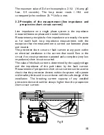
3.2 Principles of the measurement (line impedance and
prospective short circuit current)
Line impedance on a single phase system is the impedance
measured between phase and neutral terminals.
Measurement principles for line impedance are exactly the same
as for earth fault loop impedance measurement with the
exception that the measurement is carried out between phase
and neutral.
The protective short circuit or fault current at any point within
an electrical installation is the current that would flow in the
circuit if no circuit protection operated and a complete (very low
impedance) short circuit occurred.
The value of this fault current is determined by the supply voltage
and the impedance of the path taken by the fault current.
Measurement of prospective short circuit current can be used to
check that the protective devices within the system will operate
within safety limits and in accordance with the safe design of the
installation. The breaking current capacity of any installed
protective device should be always higher than the prospective
short circuit current.
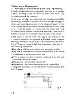
Fig 8


