


Page 19
5.3.2 Fill the central heating circuit (loosen the cap on
the automatic air vent, item 47 Fig. 6.1) &open the
manual air vent below.
5.3.3 Continue to fill until water comes out of the
manual air vent. Dose the manual air vent.
5.3.4 Repeat the process with the manual air vent until
the appliance has been thoroughly vented. If
necessary restore the pressure to about 1.2 bar.
5.3.5 Test the complete system for water soundness
5.3.6 Drain the system to rectify any leaks and refill to
the initial system design pressure venting all radiators.
DO NOT LOOSEN THE VALVE CAP ON THE EX-
PANSION VESSEL. Set the red pointer on the press-
ure gauge to the initial system design pressure.
5.3.7 Once filling is complete, ensure the water
supply valve is off, then DISCONNECT THE FILLING
LOOP AT THE OUTLET FROM THAT VALVE.
Permanent connection of the loop is not permitted.
5.3.8 Open all hot taps and allow water in flow until no
air is present. Close the laps.
5.3.9 Check the water supply connections for sound-
ness. Rectify leaks where necessary.
5.4 Fully open the remotest hot tap. and check that
the flow rate is at least 8.8 litres/min.
5.4.1 With all services checked. all valves open,
continue to commission the appliance.
5.4.2 Isolate the electrical supply.
5.4.3 Remove the boiler front panel (Section 6-2.1).
5.4.4 Light the burner {fig 1.1)
i Connect the electrical supply.
ii Select MAX on boiler control thermostat.
iri Select WINTER on the SUMMER/WINTER switch.
iv Turn on the electrical supply and set any external
controls to call for heat
v Select ON on the ON/OFF switch.
The boiler will now go through its ignition sequence
and the green light will illuminate when the burner has
lit.
If the burner fails to light, the appliance will go to
lockout (red light illuminated) In this case the cause is
probably air in the gas supply line. Wait 10 seconds.
Then press the fed button to restart the sequence.
Once lit the appliance will heal the content of the
appliance then commence supplying central heating.
5.4.6. After 10 minutes check that the burner press-
ure reading is as given in Section 2. If it is not adjust
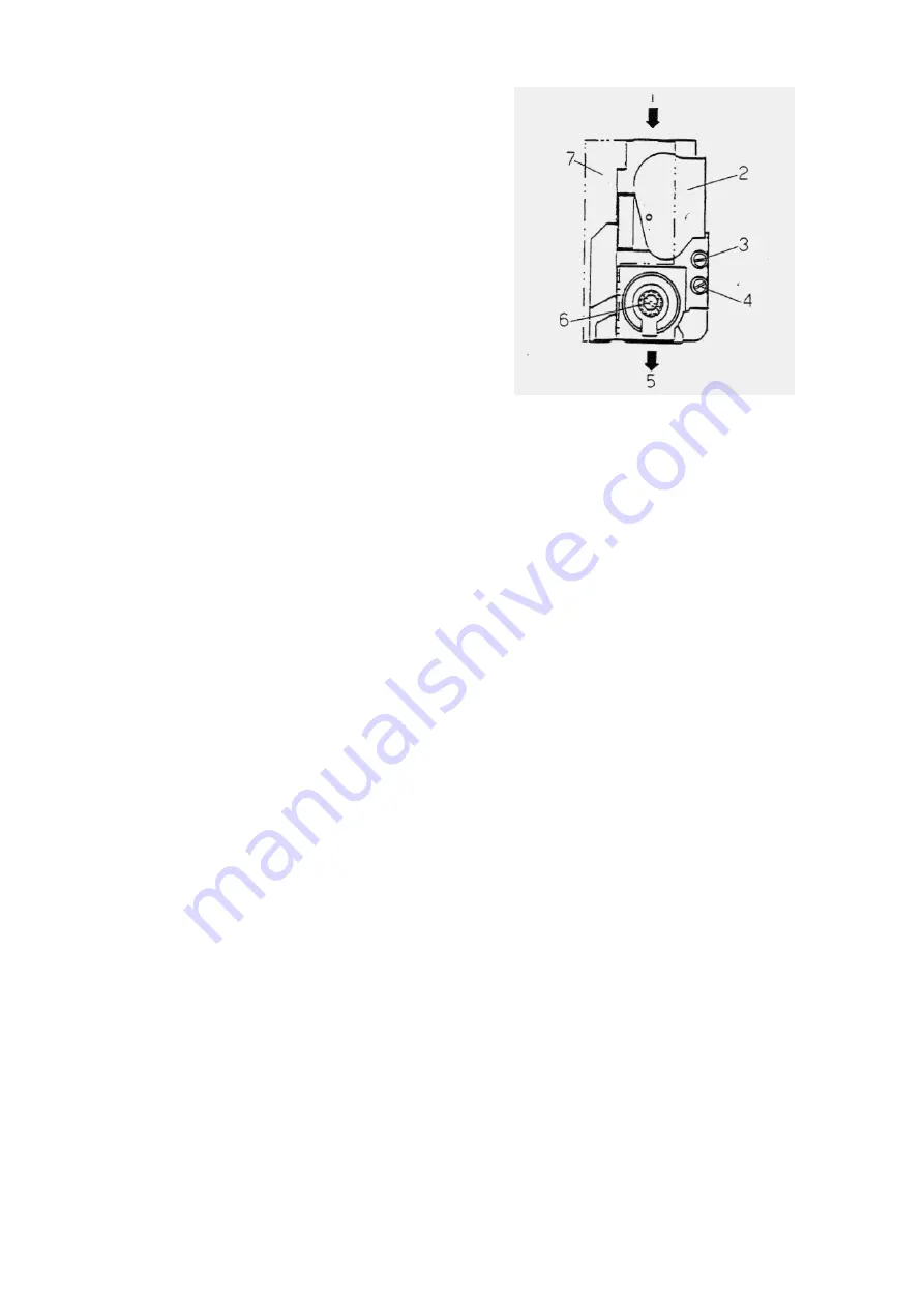
the pressure as follows (fig.5 J):
1
Gas Inlet
5
Gas outlet
2
Solenoid inlet and
protection
6
Gas pressure regulatory
screw with cap
3
Inlet gas pressure test
point
4
Outlet gas pressure
test point
7
Control box with first
step (ignition flame)
regulatory roller.
PROCEOURE TO ADJUST THE GAS PRESSURE
TO THE BURNER
Connect a suitable pressure gauge to the burner
pressure test point (fig 51 item G) The pressure
should read 14 mbar.
Remove the black dust cap covering the inlet gas
pressure lest point (fig 5.1 item 8).
Rotate the regulating screw (fig 5.1 item 3) under-
neath the cap: clockwise will decrease the pressure,
anti-clockwise will increase the pressure.
5.4.7 Open a hot tap fully, the burner will light; green
operating light ON.
5.4.8 Select SUMMER on the SUMMER/WINTER
switch Operating light ON.
5.4.9 Recheck the burner pressure.
5.4.10 Close the hot tap select OFF on the ON/OFF
switch, the burner will extinguish
5.4.11 Remove the' pressure gauge, retighten the
screw.
5.4.12Relight and check for gas soundness of the
appliance components.
5.4.13Reassemble
i Refil the base panel.
ii Relit the (rout panel
5.4.14 Relight the appliance and leave it running
checking that all air is vented, that all radiators
function and that all system controls react to various
demands.
5.5 HAND OVER THE INSTALLATION TO THE
USER
Summary of Contents for Thermomatic RSM20/FB
Page 2: ...Page 2...
Page 12: ...Page 12...
Page 17: ...Page 17...
Page 33: ...Page 33...
Page 37: ...Page 37 Complete boiler wiring schematic...
Page 39: ...Page 39 Examples of standard wiring connections to most popular models...
Page 40: ...Page 40...
Page 45: ......
Page 46: ......