Keston Thermomatic RSM20/FB Installation & Servicing Instructions Manual Download Page 16


Page 16 

If the flue length required falls between 1m and 1975 mm. 
reduce the 910 mm length of 110 mm air pipe by the 
required amount and remove the same amount from the 
plain end of the inner flue pipe. 
If the flue length required falls between 1975mm and 
2975mm. reduce the 191O mm length of 110mm air pipe 
by the required amount and remove the same amount from 
the plain end of the inner flue pipe.  
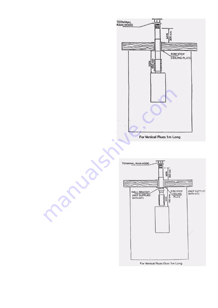
NB: The minimum height of a vertical flue is 1 metre.  
 
f Measure a distance of 113 mm from the face of the wall to 
the centre of the flue position and drill a hole of 130 mm 
diameter through the ceiling or roof above the boiler to 
receive the 100 mm diameter pipe or a hole of 145 mm 
diameter to receive the 110 mm diameter pipe. 
N6: If the ceiling is of a combustible material use a Ceiling 
Fire Stop Plate in accordance with the manu- facturers 
instruction. 
 
g Wall mount the boiler in accordance with the paras 4.3 to 
4.6. leaving a minimum distance of 450 mm above the 
boiler. 
 
h Fit the flue and air pipe extension pieces to the flue and 
air connections on the top of the Boiler i If the extended 
vertical flue kit is not being used continue the procedure 
from step q of these Installation Steps. 

For extended vertical flues only, (for tm vertical flues skip 
steps j to p): 

 
j Fix the wall bracket in the correct position to support the 
flue assembly when in place. (See Fig 4.6) 
 
k Separate the flue pipe with the terminal from the 1 metre 
length of 1OO mm diameter air pipe.  
 
I Fit the spring clips at equal intervals onto the metre length 
flue pipes from the Extended Vertical Flue Kit. m Fit the110 
mm x 100 mm reducing adaptor to the plain end of the 
metre length of 100 mm diameter air pipe so that the air 
pipe contacts the stop pins in the reducing adaptor Use the 
reducing adaptor as a template to pre-drill 2 mm diameter 
holes and secure using the screws provided. 
 
n Fully engage the 110 mm air pipe to the 110 mm x 100 
mm reducing adapter. Again use the reducing adaptor as a 
template to pre-drill 2 mm diameter holes and secure using 
the screws provided to Fit the flue pipe with terminal to the 
remaining Section(s) of flue pipe to form a complete length 
of flue pipe. Use the pre-drilled holes as a template to drill 
2 mm diameter holes and secure all connection with the 
screws provided 
 
p Push the assembled flue pipe through the assem-bled air 
pipe so that the terminal is just clear of the air pipe as 
shown in Figs 4 8 & 4 9 For 1m and extended vertical flues. 
 
q Slacken off the screws on the detachable flue pipe sleeve 
and slide over the end of the flue pipe extension piece 
attached to the outer (See fig 4 8)  
 
r Lousely assemble the  110 mm long by 60 mm diameter 
distance piece into the open end of the detachable flue 
pipe sleeve (See Fig  3) 


Summary of Contents for Thermomatic RSM20/FB

Page 1: ...UNDER FRONT PANEL ON BURNER COVER Manufactured by THERMOMATIC SRL Casalecchio Di Reno Bologna Italy exclusively for High Efficiency Domestic Commercial Boilers 34 West Common Road Hayes Bromley Kent...

Page 2: ...Page 2...

Page 3: ...91931199 Overheat thermostat Ranco LM7 P5 043 Anticondensing Thermostat Imit TR2 Electrical supply 240V 50HZ Power consumption 180 W Internal fuse rating 3A Weight empty 77 kg 169 7 Ib Weight full 92...

Page 4: ...Positioning 4 2 13 Replacing DHW Expansion Vessel 6 7 21 Flue Positioning 4 3 14 Flue Connection 4 4 14 Replacing Automatic Air Vent 6 8 21 Flue Connection 4 5 14 Replacing CM Expansion Vessel 6 9 21...

Page 5: ...ted with thermostatic radiator valves Unlike many other combination boilers the Ther momalic will operate on low water pressures The boiler within the casing is cylinder shaped and fitted with vertica...

Page 6: ...hoi water demand is satisfied the bimetallic priority thermostat allows the pump to restart When only a small domestic hot water flow is drawn the bimetallic priority thermostat does not intervene 2...

Page 7: ...he allowed value then an additional vessel must be provided connected as close as possible to the appliance heating return E Pressure relief safety valve The valve outlet must be routed to a suitable...

Page 8: ...ealed system is shown in Fig 3 3 3 3 2 Domestic hot water circuit See Fig 3 1 for connections An extended copper coil is filled which is healed from the primary water Starting from cold the appliance...

Page 9: ...ly An optional 2m extension flue system kit Pan No R3000014 is available which allows the maximum lengths to be increased lo 2840 and 2730 respective ly 3 4 4 If a vertical flue is required an optiona...

Page 10: ...icate with the same room or space or both must be on the same wall to outside air 3 5 APPLIANCE LOCATION 3 5 1 This appliance is not suitable for external installation 3 5 2 The wall on which the appl...

Page 11: ...EE Regulations and Local Regulations which apply The Thermornatic Combination Boiler is supplied for connection to a 240V 50Hz single phase The appliance is fused at 3A 3 6 2 The method of connection...

Page 12: ...Page 12...

Page 13: ...Flue hole 145 mm diameter f Insert the plastic plugs and screw in the fixing brackets to within 2 of 3 mm ol the wall face 4 3 Hang the T bar template on the fixing brackets and check that it is perfe...

Page 14: ...pipe cut from the plain end Any Flue Cut off exactly the same amount as removed from the air pipe Drill again a hole 3mm diameter at a distance of 16 mm from the end of pipe to the centre of hole e Cu...

Page 15: ...est point 2 3 1 off R3560632 Concentric roof terminal 118 length 120cm 4 1 off Roofing tile 5 b Preparations Drill a hole 130mm on the roof in axis to the fan socket If this is not possible consider t...

Page 16: ...the wall bracket in the correct position to support the flue assembly when in place See Fig 4 6 k Separate the flue pipe with the terminal from the 1 metre length of 1OO mm diameter air pipe I Fit th...

Page 17: ...Page 17...

Page 18: ...lling loop assembly to the filling cock A including the other fibre washer supplied B Ensure that the assemble filling loop does not interfere with the operation of the gas cock G Tighten all connecti...

Page 19: ...ion sequence and the green light will illuminate when the burner has lit If the burner fails to light the appliance will go to lockout red light illuminated In this case the cause is probably air in t...

Page 20: ...ig 3 JO B 6 2 4Side panels After having removed the front top and base panels remove the two screws securing the instrument panel to the respective side panel Remove the respective side panel fixing s...

Page 21: ...TIC HOT WATER EXPANSION VESSEL ITEM 46 6 7 1 Refer to Sections 6 1 6 2 1 6 2 2 6 2 4 left hand side panel 6 3 drain DHW circuit and 6 4 6 7 2 Unscrew the vessel 6 8 AUTOMATIC AIR VENT ITEM 47 6 8 1 Re...

Page 22: ...lip from the respective phial boss 6 14 4 Trace the capillary to the control body 6 14 5 Safety overheat thermostat item 65 i Unscrew the reset button cover II Disconnect two leads iii Unscrew locknut...

Page 23: ...Remove the burner sections 6 16 1 to 6 16 7 above 6 17 2 Unscrew the injectors 6 17 3 Refer to 6 16 8 when reassembling Ensure the larger injector is fitted in the center burner bar 6 18 FLAME SENSIN...

Page 24: ...reload button tripped Unscrew the black cap of safety Thermostat and push the button to restore the contact Faulty safety Thermostat ST Replace it Is the motor stuck Release the motor or replace it R...

Page 25: ...the electrode position comparing to the burner it must not touch the burner If necessary replace the electrode The fan motor starts and the red light on the instrument panel comes on Does the burner...

Page 26: ...t call for heat When the w ater temperature of the boiler exceeds 60 C does the circulation pump start check w ithout draw ing w ater See condition 6 Is the circulation pump stuck Set SWS on w inter S...

Page 27: ...ape from the various vents of the htg system Is the non return valve blocked I the domestic w ater regulatory ball valve closed No Yes No Fill the boiler and the system up to 1 bar of pressure Restore...

Page 28: ...thermostat probes are removed for servicing and w rongly fitted into the respective sheathings Restore 1 bar of pressure in the boiler and in the heating system at cold No Yes FWith the burner alight...

Page 29: ...ermostat HT set on max Set HT to position min Insufficient gas delivery No Replace HT Set the HT temperature at maximum Insulate the pipeline Set the proper pressure to the gas valve see gas valve drw...

Page 30: ...ONDITION 11 A complete cleaning is necessary Wrong fitting of the flue pipe or of the air intake pipe Gas products smell Are the fire tibes of the heat exchanger and the baffles dirty Wrong installati...

Page 31: ...the filling flexible pipe leaking Water Leakage from the boiler Does w ater escape from the air vent valve Faulty air vent valve replace it Yes Is the w ater gauge leaking Is some w asher in the hydra...

Page 32: ...3 7 Replace the baffles the inner top panel fan and the flue elbow Connect the leads polarity immaterial and the pressure tubes red to red 8 3 8 Clean any debris from the burner chamber and order 8 4...

Page 33: ...Page 33...

Page 34: ...densin g Thermostat 65 3120112 Overheat Safety Thermostat 61 3023115 Boiler Heating Regulatory Thermostat 69 303201 On Off Summer Winter Switch Key No Code Part Denomination 67 3130201 Temperature Pre...

Page 35: ...omatic Air Vent Valve 70 3520131 Operating Light Neon Bulb 71 3020157 Lamp Holder 49 3030315 C H Expansion Vessel 53 3544410 Gas Control Valve Key No Code Part Denomination 43 3424110 Bimetallic Prior...

Page 36: ...LL VALVE ALBIFIL 43 3424110 BIMETALLIC PRIORITY THERMOSTAT 46 3033315 INOX MINI VESSEL 47 3330343 AUTOMATIC AIR VENT 49 3030315 CH EXPANSION VESSEL 8 LITRES 53 3544410 GAS VALVE 59 3450113 ELECTRODE 6...

Page 37: ...Page 37 Complete boiler wiring schematic...

Page 38: ...Page 38 New Thermomatic wiring diagram as from S No 00054 When wiring the boiler in conjunction with a time switch remove the link plug from the 5 wire block left hand side at the bottom...

Page 39: ...Page 39 Examples of standard wiring connections to most popular models...

Page 40: ...Page 40...

Page 41: ...he boiler has been prepared Should it be necessary to do some adjustment for example if the supply pressure is another than the mentioned one see the specific label precede as follows 2 Connect a suit...

Page 42: ...mm of diameter through an outer wall in line with the flue bend 4 see also the dimensions in the Boiler Installation Instructions INSTALLATION l Properly position the centralising springs 9 insert the...

Page 43: ...r air pipe junction 7 1 mt Flue pipe extension 060 8 Imt Air pipe extension 0100 9 3566296 Centralising spring 10 3566293 Sealing washer fixing clamp for pipe junction 11 3566297 Finishing washer for...

Page 44: ...mp body Important Check that the pump be set at a velocity that suits the system EXPANSION TANK Remove the front panel and empty the boiler Unscrew the connection and remove the tank taking care to ca...

Page 45: ......

Page 46: ......

Reviews: