background image

11 

OSE-4-BA-e-1510 

5.4  Dioptre 

adjustment

 and focussing

A  special  feature  of  stereo  microscopes  is  that  they  are  fitted  with  an  optical  unit 
which has a relatively 

high depth of field

. In order to be able get the most benefit from

this feature, each user must synchronise the focussing mechanisms for themselves. 

The steps to do this are described in the following section. 

1. Place the object to be observed on the surface under the objective.

2. Use the objective to set the smallest possible magnification.

3. Look through the righthand eyepiece (without dioptre 

adjustment

 ring) with the

right eye and bring the object into focus by using the focus control dials.

4. Now set the largest magnification.

5. Once again, still only looking through the righthand eyepiece, bring the object into

focus

6. Then set the smallest possible zoom factor again.

7. Then  look  through  the  lefthand  eyepiece  with  the  left  eye  (with  dioptre

compensation  ring)  and  bring  the  object  into  focus,  by  turning  the  dioptre
compensation ring left or right at the right point.

8. In order to get the highest level of accuracy when adjusting the focus, you should

repeat steps 4-7.

9. In  this  way,  the  object  being  observed  will  be  in  focus  on  any  magnification

setting.

Summary of Contents for OSE 410

Page 1: ...elei 1 D 72336 Balingen E mail info kern sohn com Tel 49 0 7433 9933 0 Fax 49 0 7433 9933 149 Internet www kern sohn com User instructions Stereo microscope KERN OSE 4 OSE 410 OSE 411 OSE 413 OSE 414...

Page 2: ......

Page 3: ...ssembly 8 5 Operation and functionality 10 5 1 Getting started 10 5 2 Adjusting the interpupillary distance 10 5 3 Adjusting the magnification 10 5 4 Dioptre adjustment and focussing 11 5 5 Adjusting...

Page 4: ...cal parts in the base of the device must not be tampered with as in this area there is an additional risk of triggering an electric shock 1 2 Notes on the electrical system OSE 413 OSE 414 OSE 416 OSE...

Page 5: ...older must not be rotated back too far If you do this there is a risk that the microscope could tip over When the microscope is not being used you should fit the objective cap and cover the microscope...

Page 6: ...these are highly flammable substances You must therefore keep it away from naked flames and electrical devices which can be switched on and off and only use it in well ventilated rooms However organi...

Page 7: ...OSE 4 BA e 1510 6 2 Nomenclature Using the OSE 416 as an example with reflected and transmitted light illumination...

Page 8: ...Objective Stand Illumination OSE 410 Binocular WF 10x 20 mm 20 1x 3x Pillar OSE 411 Binocular WF 10x 20 mm 20 2x 4x Pillar OSE 413 Binocular WF 10x 20 mm 20 1x 3x Pillar 0 21W LED reflected light OSE...

Page 9: ...e the protective film which covers them When doing this make sure that you do not touch the optical lenses with your fingers In general you should avoid using two eyepieces with different magnificatio...

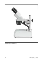
Page 10: ...9 OSE 4 BA e 1510 Assembled stereo microscope...

Page 11: ...So each time a different person uses the microscope the gap between the two eyepieces must be re adjusted While you are looking through the eyepieces use one hand to hold the righthand or lefthand pri...

Page 12: ...through the righthand eyepiece without dioptre adjustment ring with the right eye and bring the object into focus by using the focus control dials 4 Now set the largest magnification 5 Once again stil...

Page 13: ...eased On one hand this function can help to make it easier to adjust the focus and on the other hand it can prevent the microscope head from slipping down unintentionally In this way you can avoid pos...

Page 14: ...ed by the glasses symbol on the side They are also marked in the item description by an additional H example HSWF 10x 23 mm When fitting the eye cups make sure that the dioptre setting is not moved We...

Page 15: ...ight intensity cannot be adjusted OSE 416 OSE 417 reflected and transmitted light To operate the reflected and transmitted light there is a main switch on the right rear corner of the stand base surfa...

Page 16: ...quirements a goose neck lighting unit is placed next to in front of or behind the microscope The light source is in the housing of the unit and is emitted through one or several optical fibre cables T...

Page 17: ...tand Pillar without lighting Pillar with 0 21W LED lighting reflected light Pillar with 0 21W LED lighting Transmitted light and reflected light Stand inlay black white 59 5 mm OZB A4816 Frosted glass...

Page 18: ...ufficient The wrong bulb has been used The input voltage is too low Optical unit Problem Possible causes You can see two images The interpupillary distance is not set correctly The magnifications of t...

Page 19: ...materials which you can dispose of at your local recycling centre Disposal of the storage box and device must be carried out by the operator in accordance with all national or regional laws in force...

Reviews: