background image


OIV-2-BA-e-2010 

Operation and functionality  

 
When the microscope is ready for use after it has been assembled, the first step is to 
connect it to the power supply using the cable. 
 
All  important  functions  that  play  a  role  in  the  use  of  the  units  discussed  here  are 
described in the following sections. 
 

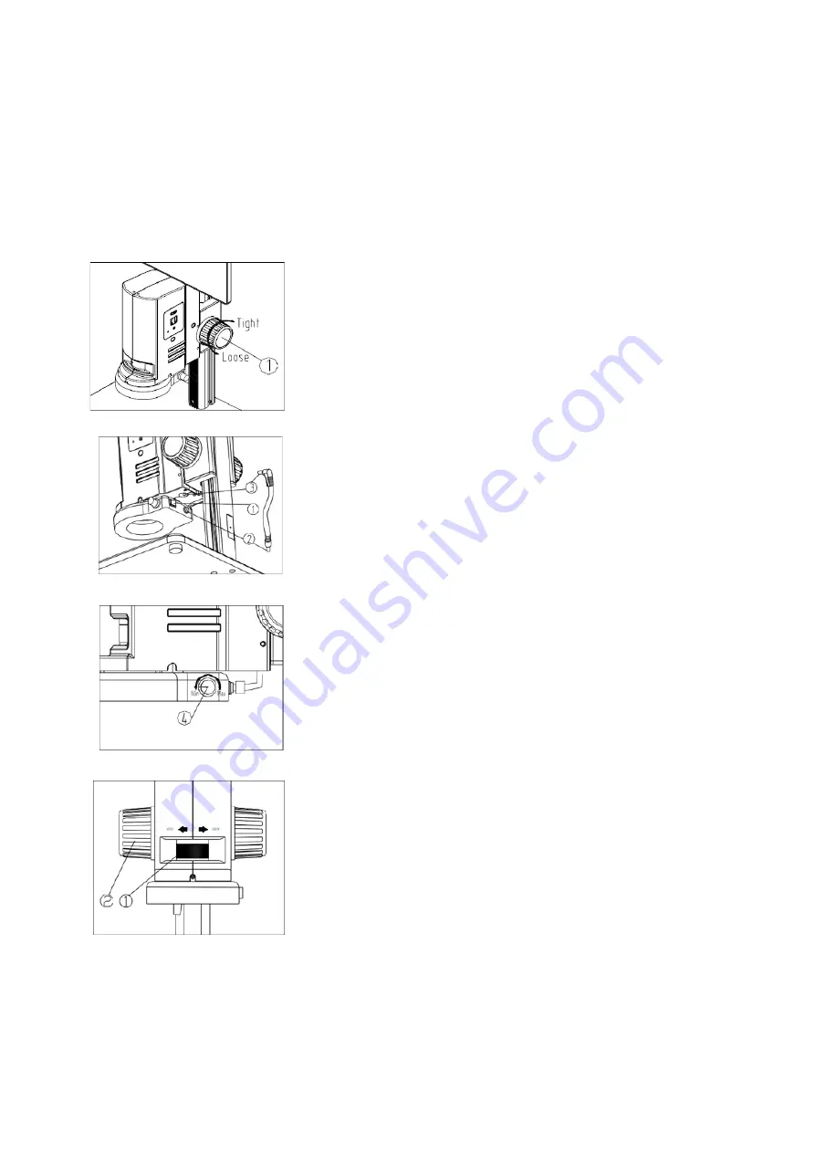
5.1  Torque of the focus wheels  

To  adjust  the  tension  of  the  focus  wheels,  hold  the  left 
wheel while turning the right wheel 

  . 

 
Be careful not to loosen the tension excessively to prevent 
the microscope from dropping under its own weight. 


5.2 

Attaching the lighting  

Connect the power cable to the ring light 

  and attach the 

other end to the microscope housing 

  . At the rear end of 

the ring light is the on/off switch 

.


5.3 

Adjusting the lighting  

Turn the wheel on the right side of the ring light to adjust 
the illumination. 


5.4  Adjusting the magnification and focus  

As the OIV series is a zoom microscope, the zoom factor 
can be changed on the adjustment wheel 

  . 

Turn the adjustment wheel to the maximum magnification. 
Focus the image using the focus wheel adjustment 

  . 

Repeat the process if necessary. 
 

The  max/min  parfocality  is  already  optimally  preset  on 
delivery. 


Summary of Contents for OIV 254

Page 1: ...N Sohn GmbH Ziegelei 1 D 72336 Balingen E mail info kern sohn com Tel 49 0 7433 9933 0 Fax 49 0 7433 9933 149 Internet www kern sohn com User instructions Video microscope KERN OIV 2 OIV 254 OIV 255 V...

Page 2: ......

Page 3: ...1 4 Maintenance and cleaning 5 2 Nomenclature 6 3 Basic data 7 4 Assembly 8 5 Operation and functionality 9 5 1 Torque of the focus wheels 9 5 2 Attaching the lighting 9 5 3 Adjusting the lighting 9 5...

Page 4: ...ptical components should therefore be left as they are found at the beginning of operation 1 2 Notes on the electrical system Before connecting to a power supply network it is important to ensure that...

Page 5: ...eded The unit should always be on a firm smooth and horizontal surface When the microscope is not being used you should cover it with the enclosed dust protective cover Dust or dirt inside the optics...

Page 6: ...e highly flammable substances It is therefore essential to keep them away from naked flames and electrical appliances that are switched on and off and to use them only in well ventilated rooms However...

Page 7: ...0 6 2 Nomenclature Screen Housing for microscope and camera LED ring illumination Microscope stand Focus wheel Zoom adjustment wheel USB connection 2 HDMI connection Snapshot button OIV 254 Power conn...

Page 8: ...m 0 7x 5x Digital zoom 9 88x 70 57x Magnification ratio 7 1 1 Screen tilt 5 15 Screen size 12 inch Screen resolution 1920x1080 HD Camera resolution 2 MP Data storage External via USB Max 128 GB Net we...

Page 9: ...housing according to the direction of the arrow Align the screw holes in ring and housing and tighten the screws 2mm Power connection Plug the power cable incl switch into the fitting plug on the mic...

Page 10: ...prevent the microscope from dropping under its own weight 5 2 Attaching the lighting Connect the power cable to the ring light and attach the other end to the microscope housing At the rear end of th...

Page 11: ...screen must be connected to the camera via HDMI in order to use the interface or the snapshot button On our OIV 255 with measuring software a mouse must be connected via USB port for operation Both o...

Page 12: ...the brightness The display does not respond Overlapping in the system too many operations leads to error loops Restart the system The focus wheel is not flexible The focus wheel is too tight Loosen th...

Page 13: ...y friendly materials that you can dispose of at local recycling points Disposal of the storage box and unit must be carried out by the operator in accordance with the valid national or regional law of...

Page 14: ...1 0 11 2020 Software System This instruction manual is for the pre installed software of the OIV 2 video microscopes Please read this manual carefully before use and keep it in a safe place The manufa...

Page 15: ......

Page 16: ...alance 5 3 3 4 Automatic exposure 5 3 3 5 Advanced Settings 6 3 3 6 Document management 10 3 3 7 Data Display 11 3 3 8 Automatic edge finding 11 3 4 Measurement functions 12 3 4 1 Operation of the mea...

Page 17: ...easuring system developed by Wise Image The powerful easy to use and customisable interface allows you to work with templates a DXF import and export function automatic edge finding and mirror functio...

Page 18: ...ed the camera to the screen 12V 1A power connection and switched it on the start screen appears as shown in 3 2 3 2 User interface As a user you can edit the user interface according to your preferenc...

Page 19: ...re elements can be changed individually 3 3 3 White balance White balance must be activated after setting the light source This can be activated in image transfer mode and is carried out by clicking o...

Page 20: ...OIV 2 SW BA e 2010 6 3 3 5 Advanced Settings...

Page 21: ...are not to be deposited with the image then No must be activated 3 3 5 2 Measurement Setup Settings Edge findig range The value of the range in which the measuring point moves for automatic edge find...

Page 22: ...easurement Setup can be adjusted 1 Measuring tool display The left side shows the measuring instruments displayed on the user interface The right side shows instruments that are not currently displaye...

Page 23: ...cking you can determine which measurement data are to be included in the Measure Data table Click on Apply to apply the applications 3 Display options of the user interface By marking you can determin...

Page 24: ...an be used to open the document management to find saved files Right click to open the submenu for the selected file The file can be deleted DEL compared with the current screen display D S Compare co...

Page 25: ...USB stick and read later as an Excel file The content of the Data Display can be adjusted as described in chapter 2 3 5 6 Note Angles broken lines and polygons cannot be changed 3 3 8 Automatic edge f...

Page 26: ...on the drawn measuring element can be picked up and moved by clicking the right mouse button The mouse pointer then takes on the shape At the end points of the elements the mouse pointer takes the sha...

Page 27: ...libration can now be done freely within the screen area By clicking the left mouse button you start the calibration line by clicking again at the end of your scale you end the calibration The followin...

Page 28: ...ate 4 Templates are automatically stored in the internal memory and can be changed and copied as needed 3 6 2 Template customization A template can be edited if it has been newly created or in customi...

Page 29: ...n The line can be moved by holding the right mouse button 4 The number of lines on the screen can be subsequently increased by The newly added lines are then also displayed with any changes made e g c...

Reviews: