SC-FI Signal Conditioner
2
INPUT & OUTPUT SETTINGS
REMOVING THE CASE:
The case must be removed to change switch settings. To
remove the case procede as follows:
Refer to FIGURE 1. Using finger tips, carefully pry the
case away from the terminal blocks (as shown with
dotted lines).
Pry far enough to release the restraining clips on both
sides of the case.
Press up on terminal block with thumbs. The assembly
will pop out allowing it to be removed from case.
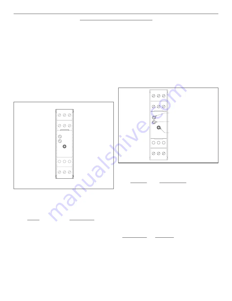
FIGURE 1:
OUTPUT ADJUSTMENTS:
The unit has two potentiometers for adjustment. The upper
potentiometer controls the 20mA setpoint and the lower
potentiometer controls the 4mA setpoint (see Figure 2). The
4mA output range can be adjusted from 3mA to 5mA. The
20mA output range can be trimmed from 50% to 100% of
the selected range. To adjust the output, initially turn the
20ma adjust 20 turns CW for starting position. Input 0
frequency and adjust the 4 mA pot. Connect your maximum
frequency and adjust the 20 mA pot.
FIGURE 2:
1 2 3
4 5 6
7 8 9
INPUT FREQUENCY RANGE SETTINGS:
The appropriate range is selected by turning “ON” the corre-
sponding switch.
Range:
Switch # “ON”
0-150Hz
1
0-300Hz
2
0-600Hz
3
0-1200Hz
4*
0-2500Hz
5
0-5000Hz
6
0-10000Hz
7
* Factory Default. The unit is setup at the factory for the
range 0-1000Hz.
RESPONSE TIME SETTING:
Switch #8 controls the output response time.
Switch #8
Response Time
OFF
0.1 second
ON
1 second
Turn switch #8 ON to provide damping of the output result-
ing in a 1 second response time.
LED INDICATOR:
The SC-FI has a LED which indicates the status of the unit.
The table below describes the 3 states for the LED.
LED STATUS:
MEANING:
OFF
The unit is off.
ON (constant)
The unit is loop powered.
BLINKING
The unit is receiving an input fre-
quency. The LED will blink at a rate
proportional to the input frequency.
(The LED may appear to be constant
at high input frequencies)
1 2 3
4 5 6
7 8 9
LED
INDICATOR
4 mA Adjust
(CCW-Down, CW-Up)
20 mA Adjust
(CCW-Up, CW-Down)
Summary of Contents for SC-FI Series
Page 2: ...THIS PAGE IS BLANK...
Page 4: ...THIS PAGE IS BLANK...


