background image

10

q

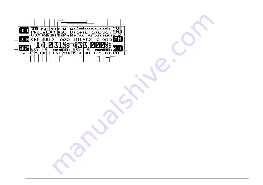
“AT” appears when you operate HF ~ 50 MHz band.
Press [L1] to activate the automatic antenna tuner.
While it is in-line, “AT IN” or “AT R IN” appears (when
Menu No. 27 is “ON”).  “CALL” appears when you
operate 144 MHz ~ 1.2 GHz bands.  Press [L1] to
recall the CALL channel for the band or press and
hold [L1] to store the new CALL channel data.

w

While “Q.IN” appears, press [L2] to store the current
frequency and other data to the Quick Memory.

e

“EASY” appears when you operate the normal
VFO/ Memory Recall mode.  Press [L3] to enter Easy
Viewing mode {page 34}.

r

Displays the current key group and its suffix number.
Press [F1] to move to next suffix number or press
and hold [F1] to move to next group {page 13}.

t

 ~ 

o

The available function name appears.  Press [F2] ~
[F6] or press and hold the key to activate the function
{pages 13 ~ 30}.

!0

The assigned function of [R2] appears.  Normally,
“RIT” appears.  Press [R2] to switch RIT ON or OFF.
Press and hold the key to clear the RIT offset
frequency.

!1

The assigned function of [R1] appears.  Normally,
“PM” appears. Press to enter Programmable Memory
function {page 41}.

!2

The main transceiver operating frequency display.

!3

When the main transceiver receives a signal or the
main transceiver’s squelch is open, “BSY” appears.
When you transmit on the main transceiver, “TX”
appears.

!4

The memory name appears when you recall the
memory channel.  “CALL” appears when you recall
the CALL channel.  “SCAN–P1” (slowest scan
speed)  ~ “SCAN–P9” (fastest scan speed) appears
while in Scan mode.

!5

“S” appears when the main transceiver is in receive
mode.  “PWR” (output power), “SWR” (SWR ratio), or
“ALC” (Automatic Level Control) appears when you
select the meter function.

!6

The memory channel number appears (3 digits) when
you recall the Memory channel.  The memory group
number “0–” ~ “9–” also appears.  When the channel
is locked out, “— — —” appears above the memory
channel number.  “Q01” ~ “Q09” appears when you
recall a Quick Memory channel.  The Satellite
memory channel number “0” ~ “9” appears in the
Satellite mode.  If no data is stored “

s

” appears

along with the memory channel number.

DISPLAY AND KEY FUNCTIONS

q

w

e

r

!3

!5

!4

t

y !6

!8

@0

u

i

o

@4

@3

@5

!0

#9 #8

!1

!2

!7

!9

@6

@7

@8

@9

#0

#1

#6 #5 #4

@1

@2

#7

#3

#2

Summary of Contents for TM-942A

Page 1: ... B62 1292 10 M 09 08 07 06 05 04 03 02 01 KENWOOD CORPORATION INSTRUCTION MANUAL MOBILE CONTROLLER RC 2000 MOBILE CONTROLLER RC 2000 ...

Page 2: ... 0 3 1 A X X 7 1 0 2 9 9 N 1 s r e t l i f e n i L e g r a l e n o h p o r c i m r o F l l a m s r e k a e p s d n a l e n a p r o F X X 9 1 4 1 9 7 L X X 7 1 4 1 9 7 L 1 2 V 2 3 A 5 2 e s u F X X 1 3 5 2 5 0 F 1 d r a c y t n a r r a W a d a n a C d n a A S U e h t r o F s e i r t n u o C n a e p o r u E r o F X X 9 6 4 0 6 4 B X X 0 1 3 0 6 4 B 1 1 l a u n a m n o i t c u r t s n I X X 2 9 2 1 2...

Page 3: ...THE FONT STYLE 36 CHAPTER 1 ABOUT THIS MANUAL BEFORE YOU BEGIN 1 PREPARATION Pages 2 6 1 QUICK START Page 7 1 KEYS AND CONTROLS Pages 8 12 1 CYCLING THE KEY GROUPS Pages 13 30 1 SATELLITE MODE Pages 31 33 1 EASY VIEWING MODE Pages 34 36 1 PACKET CLUSTER TUNE Pages 37 38 1 VISUAL SCAN Pages 39 40 1 PROGRAMMABLE MEMORY Pages 41 43 1 SKY COMMAND II Pages 44 46 1 QUICK KEY REFERENCE Pages 47 51 1 CHAP...

Page 4: ... C T MODE 38 NEW PACKET CLUSTER DATA 38 CHAPTER 9 VISUAL SCAN OVERVIEW 39 SELECTING THE NUMBER OF CHANNELS 39 USING VISUAL SCAN 40 CHAPTER 10 PROGRAMMABLE MEMORY PM PROGRAMMABLE INFORMATION 41 APPLICATION EXAMPLES 42 PM CHANNEL DEFAULT VALUES 42 STORING IN PM CHANNELS 43 RECALLING A PM CHANNEL 43 AUTO PM CHANNEL SAVE 43 CHAPTER 11 SKY COMMAND II K TYPE ONLY PROGRAMMING CALL SIGNS 44 PROGRAMMING A ...

Page 5: ...vailable on the RC 2000 Refer to the page that explains your desired key control SATELLITE MODE Pages 31 33 This chapter describes how to control the functions while ABOUT THIS MANUAL you are operating in the Satellite mode EASY VIEWING MODE Pages 34 36 This chapter describes how to control the functions while you are in the Easy Viewing mode PACKET CLUSTER TUNE Pages 37 38 This chapter describes ...

Page 6: ...000 in your vehicle you can install the transceiver in the trunk under the seat or under the dash board On the transceiver install the DC cable 7 m 23 1 ft the microphone extension cable 5 m 16 5 ft a cable for the speaker 5 m 16 5 ft a cable to the RC 2000 5 m 16 5 ft and coaxial cable s to the antenna not supplied in this package Make sure all cable lengths are adequate before installing the bra...

Page 7: ...lied self tapping screws and the 3 flat washers 4 Align the grooves on the front panel over the bracket tabs 5 Slide the front panel down until it locks in place The tab on the front panel must be completely locked by the bracket otherwise vehicle vibration may cause the front panel to become dislodged 6 Position the front panel at your desired angle then completely tighten the 2 SEMS screws on th...

Page 8: ...iver and the microphone connector as shown below MODULAR PLUG CABLE CONNECTION Use the supplied modular plug cable to connect the front panel to the main unit Connect the 4 pin plug to the front panel and 6 pin plug to the main unit Note It is easy to identify between the plugs as the 6 pin plug is slightly wider than the 4 pin plug 4 pin plug 6 pin plug Microphone extention cable Noise filter lar...

Page 9: ...bber grommet to protect the cable from abrasion Dismantle the fuse holder to pass the cable through the firewall The entire length of the cable must be dressed so it is isolated from heat moisture and the engine secondary high voltage ignition system cables 2 After the cable is in place wind heat resistant tape around the fuse holder to protect it from moisture and tie down the full run of cable 3...

Page 10: ...with the following diagram EXT SP2 8W PANEL COM ANT 2 ANT 1 ANT 144 AT ANT 1 2G DC 13 8V ANT 430 EXT SP1 8W ACC2 EXT CONT REMOTE HF RX ANT PADDLE KEY GND 2 1 RC 2000 panel External speaker Microphone To antenna Microphone extension cable DC Power cable Speaker extension cable RC 2000 cable Mounting bracket Vehicle battery 12 V ...

Page 11: ...imately the 9 o clock position Turn the MAIN SQL left outer ring control fully counterclockwise 3 Press the MAIN AF left or SUB AF right control to select the operating band The PTT icon moves to indicate which band is currently selected for the TX band The frequency information shown in a large font is selected for the current control band 4 Press F1 until you select group A 1 page 13 5 Press DOW...

Page 12: ...h R1 R2 are the two keys below the Power switch to the right of the display from top to bottom q L1 L3 key Press to activate or select the function shown on the display to the right of each key w Tuning MULTI CH RIT SUB control Normally it is used to adjust the frequency Press this control to change the control mode The current tuning control mode status appears on the top right of the display whe...

Page 13: ...ransceiver If you press this control it functions the same as MAIN on the transceiver TS 2000 page 12 y MAIN SQL control Functions the same as the MAIN SQL control on the transceiver TS 2000 page 12 u SUB AF control Functions the same as the SUB AF control on the transceiver If you press this control it functions the same as SUB on the transceiver TS 2000 page 12 i SUB SQL control Functions the sa...

Page 14: ...ssigned function of R1 appears Normally PM appears Press to enter Programmable Memory function page 41 2 The main transceiver operating frequency display 3 When the main transceiver receives a signal or the main transceiver s squelch is open BSY appears When you transmit on the main transceiver TX appears 4 The memory name appears when you recall the memory channel CALL appears when you recall the...

Page 15: ...y memory channel is selected 7 tB or Bs appears while VFO B is selected B appears while Menu B is being accessed 8 tA or As appears while VFO A is selected A appears while Menu A is being accessed 9 DSP appears when one of the DSP functions is activated 0 AGC appears when the AGC function is ON R Reverse function R Automatic Simplex Check or the Repeater shift direction or appears Note appears onl...

Page 16: ...rs only for E types 9 N R 1 appears when the Noise Reduction 1 function is ON for the sub receiver 0 TUN Tuning control MLTI MULTI CH control RIT RIT SUB control or SPED Scanning speed control appears indicating which control mode is currently assigned to the Tuning control 1 Appears when the Programmable Memory function is ON PM1 PM5 appear to indicate which Programmable Memory channel is selecte...

Page 17: ...B or C press and hold F1 As you change the group and sub group the available functions for F2 F6 change Press one of F2 F6 to activate the function which appears on the display above each key To access your desired function first select the appropriate group by pressing and holding F1 Next cycle within the group to the appropriate sub group by continuously pressing F1 The selected group and corres...

Page 18: ... I X e h t r a e l C t e s f f o y c n e u q e r f n o i t c A 3 A U N E M P E T S B N C G A F P y e k e h t s s e r P 4 A o t e v o M e d o m u n e M r e t n E e h t e g n a h C p e t s y c n e u q e r f r e k n a l B e s i o N F F O N O F F O N O C G A g o r P F P e t a v i t c A n o i t c n u F d n a s s e r P y e k e h t d l o h 1 B p u o r g o t e v o M e s i o N e h t e r u g i f n o C l e v...

Page 19: ...d to continuously cycle down through the amateur radio bands UP Press to move up the amateur radio band one step Press and hold to continuously cycle up through the amateur radio bands GROUP A 2 A B Press to alternate between VFO A and VFO B on the main transceiver SPLIT Press to activate SPLIT operation on the main transceiver TF SET When SPLIT operation is activated press and hold this key then ...

Page 20: ...new setting AGC Press to switch the AGC function ON or OFF When it is ON AGC appears on the display Press and hold to change the AGC Level TS 2000 page 38 Select the desired time constant using the b a keys or by turning the MULTI CH control then press either EXIT or the MULTI CH control to accept the new setting PF Press to activate the PF Programmable Function key assignment The default assignme...

Page 21: ...M Press to select either VFO or Memory Recall mode TS 2000 page 59 In Memory Recall mode tM or Ms appears on the display Turn the MULTI CH control to select your desired memory channel GROUP A 5 A 5 functions appear only when recalling Memory Channels 290 299 TS 2000 page 62 SET Turn the Tuning control and press SET to set the frequency point of Program Scan Partially Slowed on the main transceive...

Page 22: ... o v a d r o c e R n i 1 H C n o e g a s s e m e d o m C E R e c i o v a d r o c e R n i 2 H C n o e g a s s e m e d o m C E R e c i o v a d r o c e R n i 3 H C n o e g a s s e m e d o m C E R n o i t c A 3 B N A C S O T U A L E S G S L A U S I V y e k e h t s s e r P 4 B o t e v o M F F O N O n a c S n o i t c n u f e d o m o t u A F F O N O n a c S e h t t c e l e S p u o r G n a c S l a u s i V...

Page 23: ...une function ON or OFF page 37 TS 2000 page 53 SATL Press to switch the Satellite mode ON or OFF page 31 TS 2000 page 53 GROUP B 2 REC Press to enter stand by mode for message recording TS 2000 pages 43 89 To start recording a message press CH1 CH2 or CH3 CH1 Press to play back the message which has been recorded in channel 1 When REC is pressed and the transceiver is standing by for recording pre...

Page 24: ...al Scan function page 39 TS 2000 page 70 GROUP B 4 DUAL Press to switch the sub receiver ON or OFF CTRL Press to move the Control band to another receiver The frequency display of the Control band appears in a large font If the same band is selected for the TX band and Control band only PTT appears on the display LOCK Press to lock all the keys and controls of the RC 2000 Press and hold to unlock ...

Page 25: ... i t c A 1 C C O R P C I M N O M T R W P y e k e h t s s e r P 2 C o t e v o M r o s s e c o r P h c e e p S F F O N O t n e m t s u j d a n i a g C I M l e v e l r o t i n o M X T t n e m t s u j d a r e w o p t u p t u O t n e m t s u j d a d n a s s e r P y e k e h t d l o h 1 A p u o r g o t e v o M r o s s e c o r P h c e e p S l e v e l t u p n i t n e m t s u j d a n o i t c A 2 C X O V N I...

Page 26: ...keys or by turning the MULTI CH control then press either EXIT or the MULTI CH control to change the setting RF Refer to RF in the CW section page 24 GROUP C 3 N R Press to activate Noise Reduction 1 Noise Reduction 2 or to turn the function OFF When the noise reduction function is ON N R 1 or N R 2 appears above the key When it is ON press and hold the key to change the noise reduction level Adju...

Page 27: ... q e r f h c t i p e n o t r e w o p t u p t u O t n e m t s u j d a d n a s s e r P y e k e h t d l o h 1 A p u o r g o t e v o M n o i t c n u f e n u T W C F F O N O n o i t c A 2 C X O V Y L D K B Y E K F R y e k e h t s s e r P 3 C o t e v o M F F O N O n i k a e r B n i k a e r B e h t t s u j d A e m i t y a l e d c i r t c e l e e h t t s u j d A d e e p s r e y e k t n e m t s u j d a n i...

Page 28: ...aximum value is 255 GROUP C 3 N R Refer to N R in the USB LSB section page 22 M B C Press to switch the Manual Beat Cancel function ON or OFF Press and hold the key to enter the manual beat cancel frequency adjustment mode Adjust the beat cancel frequency using the c d keys or by turning the MULTI CH control then press either EXIT or the MULTI CH control to store the setting FILTER USB LSB FM AM m...

Page 29: ... a g X O V t n e m t s u j d a y a l e d X O V t n e m t s u j d a h t d i w d n a b w o r r a N F F O N O t n e m t s u j d a n i a g F R d n a s s e r P y e k e h t d l o h 1 A p u o r g o t e v o M n o i t c A 3 C S S C T C E N O T S C D T L A T F I H S y e k e h t s s e r P 4 C o t e v o M F F O N O S S C T C F F O N O E N O T F F O N O S C D F F O N O T L A e h t t c e l e S n o i t c e r i d...

Page 30: ...on DCS Press to activate the DCS function Press and hold the key to select your desired DCS code using the c d keys or by turning the MULTI CH control then press either EXIT or the MULTI CH control to change the setting Press SCAN to start the DCS code ID Scan ALT Press to activate the Auto Lock Tuning ALT function 1 2 GHz band only When it is ON appears SHIFT Press to select the desired repeater ...

Page 31: ... P y e k e h t d l o h 1 A p u o r g o t e v o M n o i t c A 2 C F R y e k e h t s s e r P 3 C o t e v o M t n e m t s u j d a n i a g F R d n a s s e r P y e k e h t d l o h 1 A p u o r g o t e v o M n o i t c A 3 C R N C B M R E T L I F y e k e h t s s e r P 1 C o t e v o M 1 n o i t c u d e R e s i o N F F O N O 2 r o l e c n a C t a e B l a u n a M F F O N O r e t l i f P S D e r u g i f n o C...

Page 32: ...GROUP C 2 RF Refer to RF in the CW section page 24 GROUP C 3 N R Refer to N R in the USB LSB section page 22 M B C Refer to M B C in the CW section page 24 FILTER Refer to FILTER in the CW section page 24 ...

Page 33: ... s s e c o r P h c e e p S l e v e l t u p n i t n e m t s u j d a n o i t c A 2 C X O V N I A G V Y L D V R A N F R y e k e h t s s e r P 3 C o t e v o M F F O N O X O V n i a g X O V t n e m t s u j d a y a l e d X O V t n e m t s u j d a h t d i w d n a b w o r r a N F F O N O t n e m t s u j d a n i a g F R d n a s s e r P y e k e h t d l o h 1 A p u o r g o t e v o M n o i t c A 3 C R N C B C...

Page 34: ...ction page 22 NAR Press to perform AM narrow bandwidth operation AMN appears when you operate AM narrow bandwidth RF Refer to RF in the CW section page 24 GROUP C 3 N R Refer to N R in the USB LSB section page 22 B C Refer to B C in the USB LSB setion page 22 M B C Refer to M B C in the CW section page 24 FILTER Refer to FILTER in the CW section page 24 ...

Page 35: ...lect group B 2 Confirm that you have selected group B 1 If B 1 is not selected press F1 until you select B 1 3 Press SATL n o i t c A 2 A S M V E R T E C A R T T I X e h t s s e r P y e k o t e v o M 3 A p a w S N I A M B U S d n a V E R T F F O N O E C A R T F F O N O T I X F F O N O d n a s s e r P e h t d l o h y e k o t e v o M B p u o r g T I X r a e l C t e s f f o M S Press to swap the main...

Page 36: ... kept the same Normal Trace 5 If you want to switch to the normal trace mode press T REV while in group A 2 R disappears 6 To adjust the frequency on the sub band display Press M S while in group A 2 to swap the main band with the sub band frequency then turn the Tuning or MULTI CH control The following table shows which control to use when adjusting frequencies with tracing ON and OFF e l g g o t...

Page 37: ...te Memory channel 9 to store the settings To store the settings to the Quick Memory in Satellite mode press Q IN L2 The settings are stored to Satellite Memory channel 9 To recall the Quick Memory press Q M while in group B 4 or press V M while in group A 2 then turn the MULTI CH control to recall the Satellite Memory channel 9 CHECKING THE UPLINK FREQUENCY When you need to monitor the uplink TX f...

Page 38: ...the MAIN AF control or the SUB AF control To toggle the available key functions press F1 KEYS F1 F6 Press F1 to toggle between 2 groups F appears for the first key group F appears for the second key group MODE Refer to the MODE instructions page 15 PF Refer to the PF instructions page 16 1MHz Refer to the 1MHz instructions page 15 DOWN Refer to the DOWN instructions page 15 F E D O M F P z H M 1 N...

Page 39: ...on Turn the RIT SUB control to adjust the offset frequency Press and hold the key to clear the offset page 12 XIT L2 key Press to activate the XIT function Turn the RIT SUB control to adjust the offset frequency Press and hold the key to clear the offset page 15 OFF L3 key Exit the Easy Viewing mode UP Refer to the UP instructions page 15 CLR Refer to the CLR instructions page 16 M V Refer to the ...

Page 40: ...nt styles are available To change the font 1 Press MENU 2 Turn the MULTI CH control to select Menu No 58 3 Press to select FONT2 or FONT1 default 4 Press OK to accept the change Note Changing the font in the Easy Viewing mode does not change the font in the normal display mode FONT1 FONT2 ...

Page 41: ...requency of the target DX Packet Cluster node on the sub receiver 4 Press MENU while in group A 3 then turn the MULTI CH control to select Menu No 46 Confirm that SUB is selected If not press to select SUB 5 Press P C T while in group B 1 to enter the Packet Cluster Tune P C T mode Each time new DX Packet Cluster data is received the DX station s callsign in Morse code sounds and the information i...

Page 42: ...mments of the selected DX station NEW PACKET CLUSTER DATA The transceiver can be set to output a beep instead of a Morse code when new DX Packet Cluster data is received Press MENU while in group A 3 then turn the MULTI CH control to select Menu No 49 Press SUB then turn the MULTI CH control to access Menu No 49B Select OFF VOICE can also be set when you install the optional VS 3 TS 2000 page 91 N...

Page 43: ...r level You can determine the scan range by selecting the center frequency and the number of channels The default number of channels is 61 SELECTING THE NUMBER OF CHANNELS 1 Press F1 1 s until you select group A 2 Press F1 until you select A 3 3 Press MENU 4 Turn the MULTI CH control to select Menu No 11 5 Press to select 31 61 default 91 or 181 6 Press OK to complete the setting 7 1 2 3 4 5 6 7 1...

Page 44: ...SING VISUAL SCAN 1 Select your desired frequency using the Tuning control 2 Turn the Tuning control or press Mic UP DWN to select the operating frequency This frequency will be used as the center frequency for the Visual Scan 3 Press F1 1 s until you select group B 4 Press F1 until you select B 3 5 Press VISUAL to start the Visual Scan To pause the Scan press PAUSE P appears on the display Press P...

Page 45: ...e y e k c i r t c e l E F F O N O E R P T T A F F O N O C S A d e e p s g n i n n a c S e d o m n a c S l a u s i V g n i t t e s n o i t c u d e R e s i o N y c n e u q e r f t e s f f o r e t a e p e R l o r t n o c H C I T L U M p e t s y c n e u q e r f F F O N O n w o D p U z H M 1 y c n e u q e r f n w o D p U z H M 1 p e t s F F O N O T A F F O N O C G A F F O N O e d o m e t i l l e t a S ...

Page 46: ...ctions You have to keep changing many settings each time you use the transceiver Because 5 PM channels are available up to 5 persons can separately program the transceiver and store their customized environment Then each person can quickly change to his or her favorite settings simply by recalling a PM channel It is too much trouble to change back the settings after somebody else has reconfigured ...

Page 47: ... to cancel RECALLING A PM CHANNEL 1 Press PM PM channel numbers 1 to 5 appear at the bottom of the display 2 Press 1 to 5 corresponding to your desired PM channel The contents of the selected PM channel are recalled The recalled PM channel number appears in the upper right corner To exit PM Recall mode press PM then press OFF Note You cannot recall a PM channel while transmitting AUTO PM CHANNEL S...

Page 48: ...3 3 Press MENU 4 Turn the MULTI CH control to select Menu No 62 5 Press SUB 6 Turn the MULTI CH control to select Menu No 62A 7 Press OK The Commander callsign entry prompt appears 8 Turn the Tuning control to select a character You can enter 0 to 9 A to Z and 9 Press b b b b b a a a a a to move the cursor Press DEL to delete the character at the cursor Press CLR to cancel the entry 10 Press OK to...

Page 49: ...nd the Transporter 1 Press F1 1 s until you select group A 2 Press F1 until you select A 3 3 Press MENU 4 Turn the MULTI CH control to select Menu No 62 5 Press SUB 6 Turn the MULTI CH control to select Menu No 62D 7 Press to select either 1200 bps or 9600 bps 8 Press OK to store the TNC communication speed for the Sky Command II operation Press CLR to cancel the selection Note 9600 bps can be use...

Page 50: ...trol to select Menu No 62 7 Press SUB 8 Turn the MULTI CH control to select Menu No 62E 9 Press to select either COMMAND Commander or T PORTER Transporter 10 The Sky Command II operation starts Note CLIENT is used when you use another TM D700A or TH D7A for the Transporter of the Sky Command operation Refer to USING A SEPARATE TRANSPORTER TS 2000 page 88 TO EXIT SKY COMMAND II OPERATION 1 Press ME...

Page 51: ... B 9 1 3 7 7 5 E D O M 1 A 5 1 9 1 N O M T 1 C 2 2 9 7 O T U A 3 B 0 2 3 7 V M 4 A 6 1 1 6 P U 1 A 5 1 0 1 C B 3 C 2 2 6 5 B N 3 A 6 1 7 5 L A U S I V 3 B 9 3 0 7 1 H C 2 B 9 1 9 8 R N 3 C 2 2 6 5 Y L D V 2 C 2 2 9 3 2 H C 2 B 9 1 9 8 N E P O 5 A 7 1 2 6 N I A G V 2 C 2 2 9 3 3 H C 2 B 9 1 9 8 T C P 1 B 7 3 3 5 M V 4 A 7 1 9 5 E S O L C 5 A 7 1 2 6 F P 3 A 6 1 7 7 X O V 2 C 2 2 9 3 R L C 4 A 6 1 2...

Page 52: ...7 3 O T U A 3 B 0 2 3 7 N I M 4 A 7 1 8 5 T E S F T 2 A 5 1 1 3 Y L D K B 2 C 4 2 2 4 E D O M 1 A 5 1 9 1 P U 1 A 5 1 0 1 1 H C 2 B 9 1 3 4 V M 4 A 6 1 1 6 L A U S I V 3 B 9 3 0 7 2 H C 2 B 9 1 3 4 B N 3 A 6 1 7 5 M V 4 A 7 1 9 5 3 H C 2 B 9 1 3 4 R N 3 C 2 2 6 5 X O V 2 C 4 2 2 4 E S O L C 5 A 7 1 2 6 N E P O 5 A 7 1 2 6 T I X 2 A 5 1 0 4 R L C 4 A 6 1 2 6 0 1 T C P 1 B 7 3 3 5 z H M 1 1 A 5 1 7 ...

Page 53: ... D O M 1 A 5 1 9 1 T I L P S 2 A 5 1 1 3 O T U A 3 B 0 2 3 7 V M 4 A 6 1 1 6 P E T S 3 A 6 1 7 3 1 H C 2 B 9 1 9 8 R A N 2 C 6 2 9 2 T E S F T 2 A 5 1 1 3 2 H C 2 B 9 1 9 8 B N 3 A 6 1 7 5 N O M T 1 C 2 2 9 7 3 H C 2 B 9 1 9 8 R N 4 C 2 2 6 5 E N O T 3 C 6 2 3 3 E S O L C 5 A 7 1 2 6 N E P O 5 A 7 1 2 6 L E S T 4 C 6 2 3 3 R L C 4 A 6 1 2 6 0 1 T C P 1 B 7 3 3 5 P U 1 A 5 1 0 1 L R T C 4 B 0 2 5 4...

Page 54: ...9 1 3 7 7 5 V M 4 A 6 1 1 6 P U 1 A 5 1 0 1 O T U A 3 B 0 2 3 7 B N 3 A 6 1 7 5 L A U S I V 3 B 9 3 0 7 R A C 1 C 3 2 1 5 R N 3 C 2 2 6 5 M V 4 A 7 1 9 5 1 H C 2 B N E P O 5 A 7 1 2 6 T I X 2 A 5 1 0 4 2 H C 2 B T C P 1 B 7 3 3 5 z H M 1 1 A 5 1 7 3 3 H C 2 B F P 3 A 6 1 7 7 E S O L C 5 A 7 1 2 6 E R P 1 B 9 1 7 5 R L C 4 A 6 1 2 6 0 1 R W P 1 C 2 2 9 7 0 2 L R T C 4 B 0 2 5 4 M Q 4 B 0 2 5 6 N W ...

Page 55: ... D O M 1 A 5 1 9 1 T E S F T 2 A 5 1 1 3 C B 3 C 2 2 6 5 V M 4 A 6 1 1 6 N O M T 1 C 2 2 9 7 R A C 1 C 3 2 9 2 R A N 2 C 0 3 9 2 P U 1 A 5 1 0 1 1 H C 2 B 9 1 9 8 B N 3 A 6 1 7 5 L A U S I V 3 B 9 3 0 7 2 H C 2 B 9 1 9 8 R N 3 C 2 2 6 5 Y L D V 2 C 2 2 9 3 3 H C 2 B 9 1 9 8 N E P O 5 A 7 1 2 6 N I A G V 2 C 2 2 9 3 E S O L C 5 A 7 1 2 6 T C P 1 B 7 3 3 5 M V 4 A 7 1 9 5 R L C 4 A 6 1 2 6 0 1 F P 3...

Page 56: ...center Please do not send subassemblies or printed circuit boards only Send the complete product A copy of the service report will be returned with the product SERVICE NOTE If you desire to correspond on a technical or operational problem please make your note legible short complete and to the point Help us help you by providing the following Model name Question or problem you are having Other equ...

Page 57: ...o i s n e m i D 0 2 x 4 2 x 5 5 m m 3 9 4 x 0 6 x 0 4 1 t h g i e W b l 4 0 g 0 8 1 x o r p p A EXTERNAL SPEAKER l a r e n e G r e k a e p S l a n r e t x E e c n a d e p m i r e k a e p S 4Ω 5 1 r e w o p t u p n I m u m i x a m W 5 l a n i m o n W 3 l e v e l o i d u a t u p t u O 5 8 W B d 2 e s n o p s e r y c n e u q e r F z H 0 0 0 9 0 0 3 d e d u l c n i s n o i t c e j o r P D x H x W n o ...

Page 58: ... L R E W O P t e s e R l l u F a s m r o f r e P 2 9 e g a p 0 0 0 2 S T APPENDIX 1 Press F1 POWER on the RC 2000 to switch the transceiver ON 2 To exit the demonstration mode first turn the transceiver OFF then press F1 POWER on the RC 2000 to turn the transceiver ON Note You cannot exit the demonstration mode by simply switching the transceiver OFF or performing a full reset TS 2000 page 92 CONF...

Page 59: ...INFORMATION TO THE DIGITAL DEVICE USER REQUIRED BY THE FCC This equipment has been tested and found to comply with the limits for a Class B digital device pursuant to Part 15 of the FCC Rules These limits are designed to provide reasonable protection against harmful interference in a residential installation This equipment generates uses and can generate radio frequency energy and if not installed...

Page 60: ......

Reviews: