


NXR-700
18
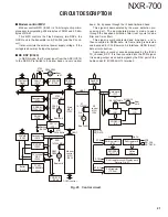
SW
+8V
+5V
CN44
+B
Q52
SW
Q32
IC24
+5V
IC16
+5V
IC17
+5V
IC18
+3V
IC10
+3.3V
IC22
+5V
Q
9
Q27
Q6
IC1
9
+8V
IC25
Q18,23
1st local amplifiers
IC14
2nd IF amplifier
IC
9
Pre-scaler
Q21,53
2nd local amplifiers
IC13
IF systemIC
Q1
9
,28
WIDE pass
SW
Q25
Q20,2
9
Narrow pass
IC15
IC12
IF system IC
Q1
LNA (Collector)
+
9
V
IC26
+
9
V
IC27
IC5,11
1st/2nd PLL
c
s
IC7
DDS
Q17,33
1st/2nd VCO buffer amplifiers
Q7,8
1st local VCO
c
s
Q24
2nd local VCO
Q2,4
active loop filter
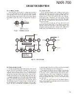
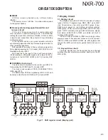
4-9. Other circuits
Other circuits include the EEPROM (IC31), the temper-
ature sensor IC (IC35), the DAC (IC23) and the ADC (IC30).
IC31 saves various adjustment values of the receiver unit.
IC35 is built-in for detecting changes in temperature. IC23
offsets the RSSI voltage (pin 1) (detected by the IF system
IC (IC12)) and the 1st-VCO_A, VCO_B control voltage (pin 2,
pin 3).
IC30 monitors the 1st-VCO control voltage (pin 16), the
LNA current detection value (pin 15), the temperature de-
tected by the temperature sensor IC (IC35 pin 14), the RSSI
voltage detected by the IF system IC (IC12 pin 12), the
squelch voltage detected by the IF system IC (IC12 pin 11),
and the control voltage of the 2nd-VCO (pin 10), and outputs
each state in serial data (IC30 pin 18), sends the signal from
CN42 (pin 22) to the control unit (X53-413). The signal is
processed by the MPU.
IC33
2nd CV
IC32
A/2
1st
VCO_A
1st
VCO_B
IC12
ASQL
IC35
TEMP.
IC6
1st CV
IC12
RSSI
IC4
LNA
10
18
11
12
14
15
16
IC30
IC31
EEPROM
5
6
1
2
6
7
8
3
IC23
CN42
11
9
8
22
32
30
Fig. 23 Other circuits
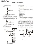
Fig. 22 AVR circuit
CIRCUIT DESCRIPTION
Summary of Contents for NEXEDGE NXR-700
Page 110: ...NXR 700 110 MEMO ...
Page 119: ...NXR 700 117 MEMO ...
Page 137: ...NXR 700 135 MEMO ...
Page 138: ...NXR 700 136 MEMO ...
Page 140: ...NXR 700 ...
Page 171: ...1 E CN300 RX_IF_VN ...


