


NXR-700
13
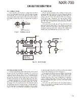
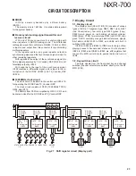
3-3. Forward/Refl ect power detector circuit
The forward / Refl ect power detector circuit consists of
a CM coupling type detection circuit formed by a Micro strip
line and the differential amplifi er IC4.
A part of the transmitter power is detected by diodes D9
and D10 and is converted into DC voltage.
ATT
IC4
Diff. AMP
D10
DET
ATT
D
9
DET
Reflect
Foward
Directional coupler
Fig. 10 Forward/Refl ect power detector circuit
3-4. Harmonic fi lter circuit
The harmonic filter circuit uses a three-stage “pi” type
Chebyshev type LPF.
This circuit removes harmonics from the transmitter out-
put and sends the fi ltered signal to the antenna connecter
(CN22).
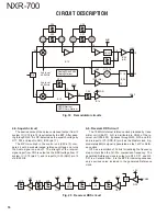
3-5. APC circuit
The APC circuit stabilizes the transmitter power so that
the output power specifi ed by the Control Voltage from the
MPU is obtained. It consists of a Forward/Refl ect power de-
tector circuit and Differential amplifi ers (IC2 and IC5).
It compares the voltage detected by the Forward/Refl ect
power detector circuit (voltage detected by the Forward
Power) and the Control Voltage (PWR_CONT) from the
MPU (IC802: X56-311 A/3). It stabilizes the output power by
changing pin 2 (Vgg).
The voltage detected (that detected Reflect Power) by
the Forward/Reflect power detector circuit is compared to
the Control Voltage (PWR_PRT) from the MPU (IC802:
X56-311 A/3). When a load V.S.W.R. is connected to the
Antenna Connecter and is more than 1.5, it functions so that
the output power gets smaller as the detection voltage (that
detected Refl ect Power) gets larger.
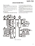
3-6. High temperature detector circuit
The high temperature detector circuit consists of a ther-
mal switch IC (IC7) and a switching FET (Q2).
This circuit lowers the transmitter power when the fi nal
unit temperature is too high (90°C or higher).
Q2
SW
Pout
VDD
VGG
Pin
IC10
RA60H1317M1A
IC7
Temp
protection
IC
Fig. 12 High temperature detector circuit
ATT
IC4
Diff. AMP
D10
DET
ATT
D
9
DET
Reflect
Foward
IC5
Add. AMP
Diff. AMP
IC2
Diff. AMP
Directional coupler
HPF
Pout
VDD
VGG
Pin
IC10
RA60H1317M1A
+
PWR_PRT
PWR_CONT
Fig. 11 APC circuit
CIRCUIT DESCRIPTION
Summary of Contents for NEXEDGE NXR-700
Page 110: ...NXR 700 110 MEMO ...
Page 119: ...NXR 700 117 MEMO ...
Page 137: ...NXR 700 135 MEMO ...
Page 138: ...NXR 700 136 MEMO ...
Page 140: ...NXR 700 ...
Page 171: ...1 E CN300 RX_IF_VN ...


