background image

RadioPro IP Gateway  

Installation and Configuration Guide NEXEDGE NX-57xx/58xx 


1.


Connect and read the control station as any other radio 


Using a Kenwood programming cable, connect the NX-5700/5800 Control Station radio to a PC or 
Notebook that has the correct Kenwood FPU version (KPG-D1N in this case). 


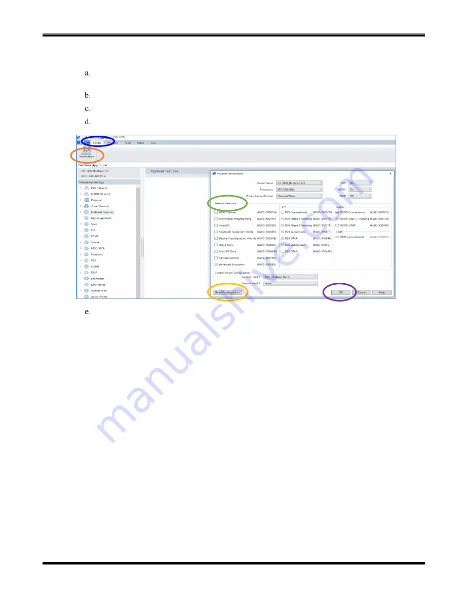
Open the 

KPG-D1N

 FPU. 


Ensure that the correct COM port is selected. 


From the 

Model 

tab, choose the 

Product Information


page, and then click the 

Read Configuration


button as shown below. 


Enable 

Feature Selections

 that this radio is licensed for with a check mark in the appropriate boxes, 

and then click the 

OK


button.  


Summary of Contents for NEXEDGE NX-57 Series

Page 1: ...CTI Products RadioPro IP Gateway Installation Guide for Kenwood NEXEDGE Radios NX 57xx 58xx Document S2 61905 828 For Version 8 Software ...

Page 2: ...oducts Inc 1211 W Sharon Rd Cincinnati OH 45240 513 595 5900 support ctiproducts com Disclaimer Information in this document is provided with best efforts for completeness and accuracy However no guarantee is expressed or implied and details may change without notice Fonts used in this document Technical terms Cross references within this document Hyperlinks to other documents or web pages Warning...

Page 3: ...1 Program the Control Station Radio 6 3 1 1 Configure the Voice Radio 6 3 1 2 Configure the Data Revert Radio 14 3 1 3 Configure Subscriber Radios 15 3 2 Connect the Gateway to the Radio 21 3 3 Configure the RadioPro IP Gateway 22 4 APPENDIX 23 4 1 Appendix Radio Interface Cables 23 Kenwood NEXEDGE NX 5700 NX 5800 NX 700 NX 800 23 5 INDEX 24 6 SYSTEM PLANNER TEMPLATE PAGE 1 OF 2 25 RadioPro IP Gat...

Page 4: ...le Contact CTI for more information 1 2 2 Control Station Radio Each Control Station radio used for voice requires one IP Gateway The control station radio connected to the IP Gateway must at least have the minimum firmware version listed below Kenwood s FPU Field Programming Unit software will be needed to configure the control station radio Control Station Radio Minimum Version Programming Softw...

Page 5: ... available Use the following table to determine if a feature discussed in this document is available System Type Feature Analog Analog w FleetSync Digital NXDN Digital NXDN w call ack NXDN LTR Trunking NXDN Trunking MsgTrnkd Voice Dispatch Text Messaging GPS Mapping Status Updates Selective Calling Not Currently Supported Not Currently Supporte d Remote Monitor Remote Enable Disa ble ...

Page 6: ...page 14 3 1 3 Configure Subscriber Radios for ARS GPS and TMS page 15 3 2 Connect RadioPro IP Gateway to Control Station Radio page 21 3 3 Configure RadioPro IP Gateway s using ICU exe page 22 Please Refer to the RadioPro IP Gateway Installation Guide for additional installation steps relevant for all radio system types 3 1 Program the Control Station Radio 3 1 1 Configure the Voice Radio For NX 7...

Page 7: ...Station radio to a PC or Notebook that has the correct Kenwood FPU version KPG D1N in this case Open the KPG D1N FPU Ensure that the correct COM port is selected From the Model tab choose the Product Information page and then click the Read Configuration button as shown below Enable Feature Selections that this radio is licensed for with a check mark in the appropriate boxes and then click the OK ...

Page 8: ...x enter a value for Fleet Own and ID Own Note These parameters do not have to be used elsewhere but they must have an assigned value even if the radio is being used in analog mode without FleetSync or in digital mode with NXDN Not entering an ID will prevent RadioPro from functioning properly d In the Unit ID box enter a value for Unit ID Note This parameter does not have to be used elsewhere but ...

Page 9: ... select Optional Features 1 b In the Optional Features 1 window expand Serial Interface and then under the Function column for COM port 1 select Data GPS Data Output c For COM Port Priority select Serial Data d For PC Interface Protocol select Version 2 e Enable all options for Serial Output and Serial Input with a check mark in the appropriate boxes ...

Page 10: ...ro can process GPS information from subscriber radios the control station radio must know what data to send to the IP Gateway Configure this as follows a Expand the Optional Features folder then select Optional Features 2 b In the Base Station Settings section of the GPS page enable PKLDS PKNDS KW with a check in the box ...

Page 11: ...lect FleetSync Information b Enable all options in the Serial Output section except for Transparent Header c Enable all options in the Stack section 6 Configure NXDN Settings a Expand the NXDN folder then select NXDN Information b Enable all options in the Serial Output section except for Transparent Header c Enable all options in the Stack section ...

Page 12: ...58xx 12 7 Configure Sound Options The steps in this section may be skipped if this radio is to be used for GPS only ie not used for voice communications a Select the Audio Profile folder b In the General section of the Audio Profile page change Microphone Sense to 4 dB High ...

Page 13: ...teps in this section may be skipped if this radio is to be used for GPS only ie not used for voice communications a Select the Extended Function folder b Expand the Modulation Line tab c For Mic PTT select Connect for both Mic Line and MI2 Line 9 Write New Configuration to Radio a Click the icon found in the main toolbar ...

Page 14: ...ld for the Voice Radio with the following exceptions Because the Data Revert Radio does not deal with audio you may skip the steps for Configure Sound Options on page 12 as well as steps for Configure Audio Routing Options on page 13 Be certain to follow steps described on page 10 Configure GPS Settings Because Channel Steering only affects the Voice Radio program only the data channel into the ra...

Page 15: ...r radio a Using a Kenwood programming cable connect the NX 5200 5300 Control Station radio to a PC or Notebook that has the correct Kenwood FPU version KPG D1N in this case b Open the KPG D1N FPU c Ensure that the correct COM port is selected d From the Model tab choose the Product Information page and then click the Read Configuration button as shown below e Enable Feature Selections that this ra...

Page 16: ...tion window for System Type select Analog Conventional and for Signaling Type select FleetSync Enter a value for Fleet Own and ID Own 3 Or Configure ID settings for NXDN If using NXDN expand the Personal folder expand the System 1 folder under that and then select System Information In the System Information window for System Type select NXDN Conventional and for Signaling Type select FleetSync En...

Page 17: ... conventional non trunked system use the Analog section to ensure that the correct data will be sent to the Data Channel i Specify the channel to use for data by assigning the Data Zone Channel Analog field as required for your system ii Enable the desired messages to send across the Data Zone Channel with a Check iii Enter a value For Target Fleet and Target ID Note If the target does not include...

Page 18: ... will be sent to the Data Channel i Specify the channel to use for data by assigning the Data Zone Channel NXDN field as required for your system ii Enter a value for Base ID Type and Base ID iii Enable the desired messages to send across the Data Zone Channel with a Check Note If the Base ID does not include the Control Station s data will not be sent to RadioPro clients ...

Page 19: ...iguration Guide NEXEDGE NX 57xx 58xx 19 5 Configure Text Message Settings Select the Key Assignment folder in the Menu section choose Call in the Category List select Short Message from the Available Function List and then click the Add button ...

Page 20: ...check mark and then select the correct channel to use in the GPS Report Channel box Ensure the GPS Base ID Type includes the Control Station radio i If using GPS with NXDN in the NXDN section enter a value for GPS Base ID Type and GPS Base ID ii If using GPS with FleetSync in the FleetSync section enter a value for Base Fleet and Base ID Note This is the ID the subscriber will respond to which wil...

Page 21: ... the DE 9 male side of the cable to the DE 9 female connector on the rear of the IP Gateway 3 Ensure that jack screws on both connectors are tightened to hold connectors in place Connect the IP Gateway to the Data Revert Control Station radio using the following steps 1 Connect the DB 25 side of cable 89 10505 DB25 Male to DE9 Female to the DB 25 connector on the rear of the NEXEDGE NX 800 radio 2...

Page 22: ...connected to the IP Gateway with the ICU Utility NEXEDGE Radio tab Enter the appropriate radio ID values for the fields on this tab The Receive PTT ID timeout ms field is used to give the transmitting radio time to transmit its PTT ID before the default PTT ID is used GPS tab If mapping locations of subscribers is required place a check mark next to Start GPS polling when online status received Le...

Page 23: ...audio to radio 5 25 Rx Speaker audio from radio Transformer isolated 600 ohms 8 17 Rx speaker audio from radio 9 18 Tx Data from radio 1 3 Rx Data to radio 6 2 Digital Ground 3 7 Interface cable requires DE 9 Male to connect to the IP Gateway female connector Data Radio Interface Cable 89 10505 standard DE 9 to DB 25 serial cable Signal Name IP Gateway DE 9 Pin NXx00 Radio DB 25 Pin Tx Data from r...

Page 24: ...gs 10 I ICU 25 GPS tab 22 NEXEDGE Radio tab 22 IP Addressing 25 IP Configuration Utility 22 K Key Assignment 19 KPG 111DN 4 KPG D1N 4 6 7 15 M Mic PTT 13 Microphone Sense dB 12 Modulation Line 13 N NTP Server IP 25 NXDN Conventional 8 NXDN Settings 11 P Password 26 PC Interface Protocol 9 R Receive PTT ID timeout 22 S Start GPS polling 22 Subnet Mask 25 System Planner Template 25 26 T Text Message...

Page 25: ...hars per line Serial IP Address Subnet Mask Default Gateway IP Gateway A Example Gateway Name 1234 192 168 56 22 255 255 255 0 192 168 56 1 Voice Radio A0 Example Radio VR A0 192 168 10 1 255 255 255 0 GPS Radio A1 Example Radio GPS A1 192 168 11 1 255 255 255 0 IP Gateway B Voice Radio B0 GPS Radio B1 IP Gateway C Voice Radio C0 GPS Radio C1 IP Gateway D Voice Radio D0 GPS Radio D1 IP Gateway E V...

Page 26: ...s to each Dispatch client Administrator Password for Edit Mode PC Name IP Address License Licensed IP Gateway Connections RadioPro Solo Talk and Mobile Clients See RadioPro Solo Client Installation Guide S2 61568 for more information Parameters Common to all Talk Clients Administrator Login Name Not Editable Administrator Password default is admin admin User Login Name default is user User Passwor...

Reviews: