DPC-885
6
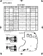
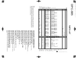
ADJUSTMENT
No.
2
1
LASER
POWER
–
Apply the sensor
section of optical
power meter on
the
pickup lens.
Short the test land. Confirm
that the display is
" ".
Press FF Key and confirm
that the display is 03.
–
On the power from
0.08 to 0.15 mW,
when the diffraction
grating is correctly
aligned with the RF
level of 1.0 Vp-p or
more.
–
3
4
5
ITEM
FOCUS
ERROR
TRACKING
ERROR
FOCUS
GAIN
TRACKING
GAIN
INPUT
SETTING
Test disc
KTD-03
Test disc
KTD-03
Test disc
KTD-03 Apply
signal of
1.0kHz,
0.05Vrms
between
Check-land
FE1 and FE2.
Test disc
KTD-03 Apply
signal of
1.0kHz,
0.05Vrms
between
Check-land
TE1 and TE2.
OUTPUT
SETTING
Connect an
oscilloscope as
follows.
CH1:RF
(Check-land RF)
CH2:TE1
Press the FF key.
Confirm that the display is
" ".
Connect a LPF
between Check-
land FE1 and FE2
to which connect an
oscilloscope or AC
voltmeters.
Connect a LPF
between Check-
land TE1 and TE2
to which connect an
oscilloscope or AC
voltmeters.
Connect an
oscilloscope as
follows.
CH1:RF
(Check-land RF)
CH2:TE1
PLAYER
SETTING
Press the PLAY key .
Confirm that the display is
"05".
Press the PLAY key .
Confirm that the display is
"05".
Press the PLAY key .
Confirm that the display is
"05".
ALIGNMENT
POINT
TE
BALANCE
VR5
FOCUS
GAIN
VR4
TRACKING
GAIN
VR6
FE
BALANCE
VR3
ALIGN FOR
Optimum eye pattern
Symmetry between
upper and lower
Two VTVMs should
read the same
value.
Two VTVMs should
read the same
value.
FIG.
–
–
(d)
(e)
L.P.F
L.P.F
FE1
FE2
AC voltmeter
GND
1.0kHz
0.05Vrms
L.P.F
L.P.F
TE1
TE2
AC voltmeter
GND
1.0kHz
0.05Vrms
TEST
RF
VR3
FB
T.B
VR5
VR6
VR4
VC
TG
FG
TE2
FE2
FE1
TE1
Note: Test DISC KTD-03, TCD-783 or equivalent
LPF : Around 47k
Ω
+ 390 pF or so.
Step 1~5 are in Test Mode.
(d) Focus Gain
Two VTVMs should read the same
value.
(e) Tracking Gain
Two VTVMs should read the same
value.
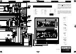
Check-lands and
alignment point
COVER/CIR/EXP-INT
98.4.24
2:57
PM
y [ W
6

