DP-1100B II
1. CIRCUIT DESCRIPTION
1-3 PROCESS CIRCUIT
1-3-1 E F M signal demodulation
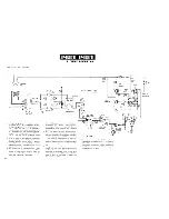
T h e EFM signal (EFMO) o u t p u t f r o m pin 4 1 of I C 1 5 o n t h e
s e r v o PCB is i n p u t t o p i n 5 2 (EFM 2) of IC8 a n d pin 1 4 (EFMI)
of IC9 o n t h e p r o c e s s PCB.
IC9 w o r k s as a digital PLL t o g e t h e r w i t h V C O Q 3 . Signal EFMI
is p h a s e - c o m p a r e d w i t h signal PLCK ( 4 . 3 2 M H z ) r e s u l t a n t
f r o m 1/4 f r e q u e n c y d i v i s i o n of signal V C O I .
H e r e , w h e n signal PLCK is d e l a y e d f r o m signal E F M I , pin \ J
O U
T
b e c o m e s " L " a n d a c t s t o m a k e t h e V C O f r e q u e n c y h i g h e r .
C o n v e r s e l y , w h e n it is a d v a n c e d , pin D
OU
T
b e c o m e s " H " a n d
a c t s t o m a k e t h e V C O f r e q u e n c y l o w e r .
T h e EFM signal o u t p u t f r o m pin D
OU
T
in s y n c h r o n i z a t i o n w i t h
t h e rising e d g e of signal PLCK is f e d t o pin 5 3 (EFMI) of I C 8 ,
in w h i c h d e t e c t i o n is m a d e t o a f r a m e s y n c signal w h i c h is a
c o n t i n u o u s signal of 11 " H " bits a n d 11 " L " bits.
W h e n t h e f r a m e s y n c signal is o b t a i n e d , t h e EFM signal is
d e m o d u l a t e d into a n 8 - b i t s i g n a l . M o r e o v e r , the u s e r ' s bits
j u s t after t h e f r a m e s y n c signal are d e m o d u l a t e d a n d data Q
a m o n g t h e m are d i s p l a y e d as t i m e data b u n d l e d by 9 8
f r a m e s . T h e s e are also u s e d in FF or B W D o p e r a t i o n , e t c .
T h e m u s i c d a t a , c o n v e r t e d f r o m 1 4 - b i t t o 8 - b i t s i g n a l s , are
w r i t t e n in jitter a b s o r p t i o n m e m o r y IC7 u n d e r c o n t r o l of IC6
( T C 9 1 7 9 F ) . T h e o n e - f r a m e 3 2 - s y m b o l data is c o r r e c t e d f o r
e r r o r in t h e C1 c o r r e c t i o n s e c t i o n . N e x t , after d e - i n t e r l e a v e
o p e r a t i o n , t h e d a t a w h i c h c o u l d n o t be c o r r e c t e d in the C1
c o r r e c t i o n s e c t i o n is c o r r e c t e d in t h e C 2 c o r r e c t i o n s e c t i o n .
O n l y t h e data w h i c h c o u l d n o t be c o r r e c t e d e v e n in t h e C 2
c o r r e c t i o n s e c t i o n is s u b j e c t t o m e a n - v a l u e i n t e r p o l a t i o n a n d
is o u t p u t t o t h e D/A c o n v e r t e r .
1 - 3 - 2 C L V s e r v o control in I C 8 ( T C 9 1 7 8 F )
a) A F C
T h e signal r e s u l t a n t f r o m 1/4 f r e q u e n c y d i v i s i o n of f r a m e
sync signal a n d t h e i n p u t s i g n a l ( 2 . 1 1 6 8 M H z ) f r o m C 2 1 K
are u s e d h e r e . T h e n , w i t h t h e c e n t e r of t h e c o u n t of 1 1 5 2
c l o c k pulses of C 2 1 K in r e s p e c t t o t h e f o r m e r s i g n a l , pin 2 0
(AFCO) o u t p u t s a 0 V signal w h e n t h e s p e e d of t h e disc m o t o r
rises a b o u t 1 0 % a n d o u t p u t s a 5 V signal w i t h t h e s a m e
v o l t a g e as v o l t a g e V D D w h e n t h e s p e e d l o w e r s a b o u t 1 0 % .
T h u s , in the r a n g e of ± 1 0 % c h a n g e in m o t o r s p e e d , t h e o u t
p u t v o l t a g e c o r r e s p o n d s t o m o t o r r e v o l u t i o n ( P W M w a v e ) .
b) A P C
P h a s e - c o m p a r i s o n is m a d e b e t w e e n t h e signal r e s u l t a n t f r o m
118 f r e q u e n c y division o f t h e f r a m e s y n c signal a n d t h e signal
f r o m a f r e q u e n c y d i v i s i o n of signal C 2 1 K . T h e c o m p a r i s o n
o u t p u t is e m i t t e d as P W M signal w i t h 8 - b i t r e s o l u t i o n . H e r e ,
V D D / 2 ( 2 . 5 V) is o u t p u t at a p h a s e d i f f e r e n c e o f z e r o in a
c o n t r o l range of ± 7 / 8 ir.
In a d d i t i o n , t h e s p e e d of t h e disc m o t o r c a n be c o n t r o l l e d by
signal D I V + or D I V - f r o m T C 9 1 7 9 F . For i n f o r m a t i o n a b o u t
T C 9 1 7 8 F a n d T C 9 1 7 9 F , refer t o t h e d i a g r a m o n p a g e s 8 1
t o 9 0 .
37
Summary of Contents for DP-1100 B
Page 3: ...D P 1 1 0 0 B II D P 1 1 0 0 B II I BLOCK DIAGRAM ...
Page 32: ...D P 1 1 0 0 B II 1 CIRCUIT DESCRIPTION Disc Scratch Dust RFES D C O N D O C K Fig 1 2A 3 5 ...
Page 112: ...2 IC OPERATION OF EACH CIRCUIT AND D P 1 1 0 0 B II PIN DESCRIPTION Fig 2 4 1 G 1 ...
Page 117: ...DP 1100B II I OPERATION OF MAIN MICROPROCESSOR Fig 3 1D Q data reading flow chart ...


