


24
·
146.03358410
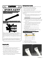
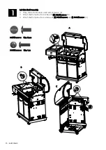
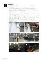
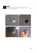
Left Side burner
□
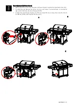
Remove plastic packaging from side burner valve. Remove side burner grate from within
side burner shelf.
□
Connect flat igniter wire tip to the igniter pin on the side burner valve. (A & B)
□
Remove the 2 pre-installed screws from the valve control stem and set them aside. (C)
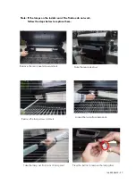
□
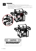
Loosen the side burner to insert gas valve. To loosen, remove the two screws on front bracket,
and loosen the rear bracket screws halfway. (D&E)
□
Insert the gas valve into the side burner (F), and insert the valve control stem through the hole
in shelf fascia. (I)
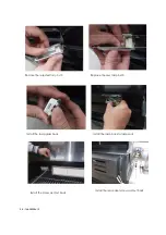
□
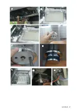
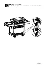
Replace side burner front bracket and tighten in place with 2 previously removed screws. (G)
Tighten screws on back bracket. (H)
□
Install previously removed 2 screws .Note:Do not tighten these 2 screws until the bezel is attached
to fascia and valve face.(I).
□
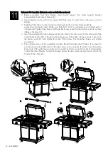
Attach bezel to facial and valve face with the installed screws .First attach one side key hole of
bezel to the screw ,then attach the other one to the other screw.Make sure the black mark faces
up.(J). Tighten the 2 screws .(K)
□
Push control knob onto side burner valve stem. (L) Replace side burner grate. (M)
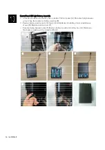
□
Connect the round igniter wire tip to the pin on the white electrode protruding from the bottom
of the side burner shelf. (N)
A
C D
E F
B
Summary of Contents for 146.03358410
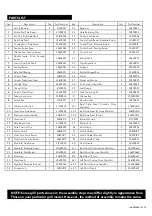
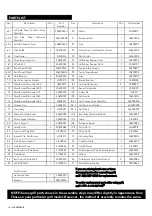
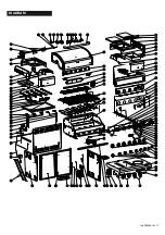
Page 17: ...DIAGRAM PARTS LIST 146 03358410 17 ...
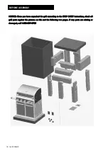
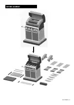
Page 19: ...146 03358410 19 BEFORE ASSEMBLY ...
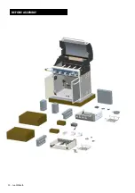
Page 20: ...20 146 03358410 BEFORE ASSEMBLY ...
Page 25: ...146 03358410 25 G H I J K L I K L M N J ...
Page 27: ...146 03358410 27 F G H J K L M N I ...
Page 57: ...ESQUEMA PARTS LIST 146 03358410 57 ...
Page 59: ...146 03358410 59 ANTES DE ASAMBLEA ...
Page 60: ...60 146 03358410 ANTES DE ASAMBLEA ...
Page 65: ...146 03358410 65 G H I J K L I J K L M N ...


