background image

HiArc S 400R, 400A

12

EN

3.4  tig welding

TIG welding is possible only with HiArc S 400A model, not with the R model.

NOTE! 

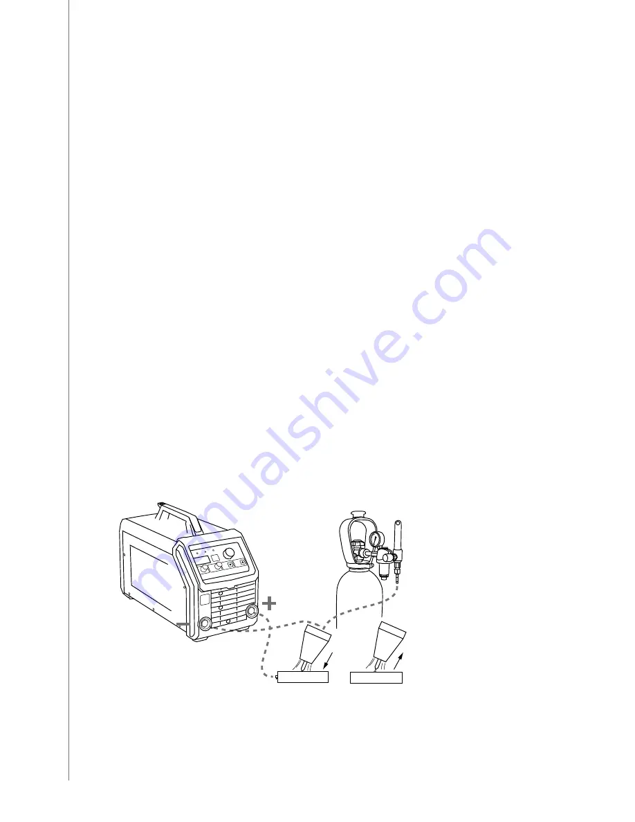
In TIG welding the welding cable must be connected to the negative (-) pole connection 

socket and the earth return cable to the positive (+) pole connection socket.

Select your required welding parameters according to the manufacturer’s filler material 

recommendations and the joint to be welded.

1. 

Select the required polarity of welding current cable (-) and earth return cable (+) for TIG 

welding.

2. 

Select TIG welding mode by pressing the process selection button on the control panel.

3. 

Select a suitable welding current by adjusting the current adjustment knob.

4. 

Make a small test weld to check the selections made.

Shielding gas is used in DC TIG welding. Your dealer will give you advice on choosing gas and 

equipment.
You can start welding after having made the necessary selections. Open the gas valve on the 

TTM 15 V BC. When gas starts to flow, arc is lit by lightly scratching work piece with the tip of 

the tungsten electrode, or with the touch and lift method (see 'Ignition by Lift TIG'). When arc 

is lit, its length is regulated by holding the tip of the tungsten electrode at a suitable distance 

from the work piece. Suitable arc length is usually about half the diameter of the electrode 

core wire. Move the torch forwards from the starting point. If necessary, adjust current value.
The filler material, tungsten electrode and the welding current level are decided according to 

the base material type and thickness, joint form and welding position.
Stop welding by lifting the torch off the welding piece and by closing the gas valve on the 

torch.

NOTE!  

The torch voltage will remain on.

NOTE!  

Always fix the gas cylinder so that it stays steadily in upright position either in specially 

made wall rack or cylinder trolley. Always close the cylinder valve after having finished welding.

ignition by lift tig
You can ignite TIG arc with the Lift TIG method. Gently touch the work piece with the 

electrode and quickly lift the electrode from the work piece to a suitable welding distance to 

ignite the arc. If electrode contact with the work piece exceeds 1 second, the power source 

ignition will automatically shut off preventing damage to the electrode.
To stop welding, quickly pull the electrode away from the work piece.

< 1.0 s

Order information for the additional equipment (TIG torch) required for TIG welding can be 

found in 'Ordering codes' section later in this manual.

Summary of Contents for HiArc S 400A

Page 1: ...HiArc S 400R 400A EN ES FR PT RU Operating manual Manual de instrucciones Manuel d utilisation Manual de utilização Инструкции по эксплуатации ...

Page 2: ......

Page 3: ...Operating manual English ...

Page 4: ...rc S 400R 7 3 2 3 Activation and setup parameter adjustment HiArc S 400R 7 3 2 4 Control panel and SETUP functions HiArc S 400A 8 3 2 5 Activation and setup parameter adjustment HiArc S 400A 9 3 3 MMA welding 10 3 3 1 Filler materials and equipment 10 3 3 2 Earth return cable and clamp 10 3 3 3 Manual metal arc welding MMA 10 3 3 4 Electrode welding parameter table 11 3 3 5 Arc force HiArc S 400A ...

Page 5: ...to change without prior notice Important notes Items in the manual that require particular attention in order to minimise damage and personal harm are indicated with the NOTE notation Read these sections carefully and follow their instructions Disclaimer While every effort has been made to ensure that the information contained in this guide is accurate and complete no liability can be accepted for...

Page 6: ...y selection button 5 Welding current adjustment knob 6 Negative pole connection socket earth return cable 7 Positive pole connection socket welding cable 8 Main switch ON OFF 9 Mains power cable HiArc S 400A 1 3 5 7 10 4 6 14 8 2 9 11 12 13 1 Power on pilot lamp 2 Overheating pilot lamp 3 Amperage voltage meter display 4 Amperage voltage meter display selection button 5 ArcForce 6 HotStart ...

Page 7: ...onment This machine is suitable for both indoor and outdoor use Always make sure that the air flow in the machine is unrestricted The recommended operating temperature range is 20 50 C Please read also the Safety Instructions concerning the operating environment 2 2 Positioning of the machine Place the machine on a sturdy level surface that is dry and does not allow dust or other impurities to ent...

Page 8: ...ble directly onto work piece 1 Clean contact surface of the clamp from paint and rust 2 Fasten the clamp properly so that contact surface is as large as possible 3 Check that the clamp is fastened firmly 3 Operation NOTE Weldinginplacespresentinganimmediatefireorexplosionhazardisforbidden Welding fumes may cause injury take care of sufficient ventilation during welding 3 1 Welding processes 3 1 1 ...

Page 9: ...urrent value when not welding 3 2 3 Activation and setup parameter adjustment HiArc S 400R 1 Press A V selection button 3 for at least 3 seconds until the text Set appears on the screen 2 Choose the needed parameter with the welding current adjustment knob 4 3 To select the required parameter press the A V selection button 3 You can move from adjustment mode to selection mode with a new press of b...

Page 10: ...4 Amperage voltage meter display selection button Short press to select either amperage or voltage values to the display Values can be adjusted during welding Long press 5 s activates setup function 5 Welding current adjustment knob Turn the knob to set the welding current value 6 Amperage voltage meter display Shows used current voltage values during welding and the set current value when not wel...

Page 11: ...tion is On the machine cuts off the power and protects the electrode if sticking occurs during the welding On On OFF Cab Long cables Long cable mode for welding circuits of 50 m and longer max 80 m OFF On OFF Gen Generator Generator mode for generator use and fluctuating mains networks OFF On OFF rcL Remote Low Current limit Limits the remote adjustment range Allows more exact remote adjustment 30...

Page 12: ...ata section later in this manual Follow the welding specifications given on the electrode package 1 Check that the welding cable and earth return cable connections are hand tight If a cable connection is loose it will result in a decrease of welding performance overheating of the connection and it may affect your product warranty cover 2 Select and mount the correct electrode type firmly in holder...

Page 13: ...ing by moving the welding electrode slightly back to the completed weld and then lifting the electrode straight away from the work piece Your completed weld bead should be straight and of even width and bead height consistent in its appearance Travel too slowly during welding and the weld pool will get too big and may burn through the weld piece too fast and the resulting weld will be too small an...

Page 14: ...ted by holding the tip of the tungsten electrode at a suitable distance from the work piece Suitable arc length is usually about half the diameter of the electrode core wire Move the torch forwards from the starting point If necessary adjust current value The filler material tungsten electrode and the welding current level are decided according to the base material type and thickness joint form an...

Page 15: ...n any oxidised parts and tighten any loose ones NOTE You must know the correct tension torques before you start repairing the connections Clean the inner parts of the machine from dust and dirt e g with a soft brush and a vacuum cleaner Do not use compressed air because there is the danger that the dirt is packed even more tightly in the gaps of the cooling profiles Do not use a pressure washer NO...

Page 16: ...connected Check the mains fuses replace blown fuses Check the mains cable and plug replace defect parts The machine is not welding properly Welding creates spatter The weld joint is porous or power supply is insufficient Check the welding parameter settings and adjust if needed See welding parameter table on page 9 Check that the earth return clamp is properly fastened and that earth return cable ...

Page 17: ...ne shuts down model R Ensure free air flow Let the machine cool down Check the environment temperature Error 9 E9 Mains network phase alarm Check the mains network connection and fuses If connected to generator check setup jumper Gen Error 10 E10 Error 11 E11 VRD error Error 12 E12 Power source is locked Too long short circuit Machine stops welding model A Machine shuts down model R Avoid long sho...

Page 18: ...A 36V MMA 100 ED 310 A 32 4V 310 A 32 4V TIG 60 ED 400 A 26V TIG 100 ED 310 A 22 4V Welding voltage max 400 A 48V 400 A 48V Electrodes ø 1 6 7 0 mm 1 6 7 0 mm Welding current control stepless stepless Power factor at 100 0 90 0 90 Operating temperature range 20 50 C 20 50 C Efficiency at 100 0 89 0 89 Degree of protection IP23S IP23S EMC class A A External dimensions L xW x H 570 x 270 x 340 mm 57...

Page 19: ......

Page 20: ...7792 0 Telefax 49 6 403 779 79 74 sales de kemppi com KEMPPI SPÓŁKA Z O O Ul Borzymowska 32 03 565WARSZAWA POLAND Tel 48 22 7816162 Telefax 48 22 7816505 info pl kemppi com KEMPPI AUSTRALIA PTY LTD 13 Cullen Place P O Box 5256 Greystanes NSW 2145 SMITHFIELD NSW 2164 AUSTRALIA Tel 61 2 9605 9500 Telefax 61 2 9605 5999 info au kemppi com OOO KEMPPI Polkovaya str 1 Building 6 127018 MOSCOW RUSSIA Tel...

Reviews: