


6
A5 MIG Rail System
© Kemppi Oy 2021
R01
OPERA
TING M
ANU
AL
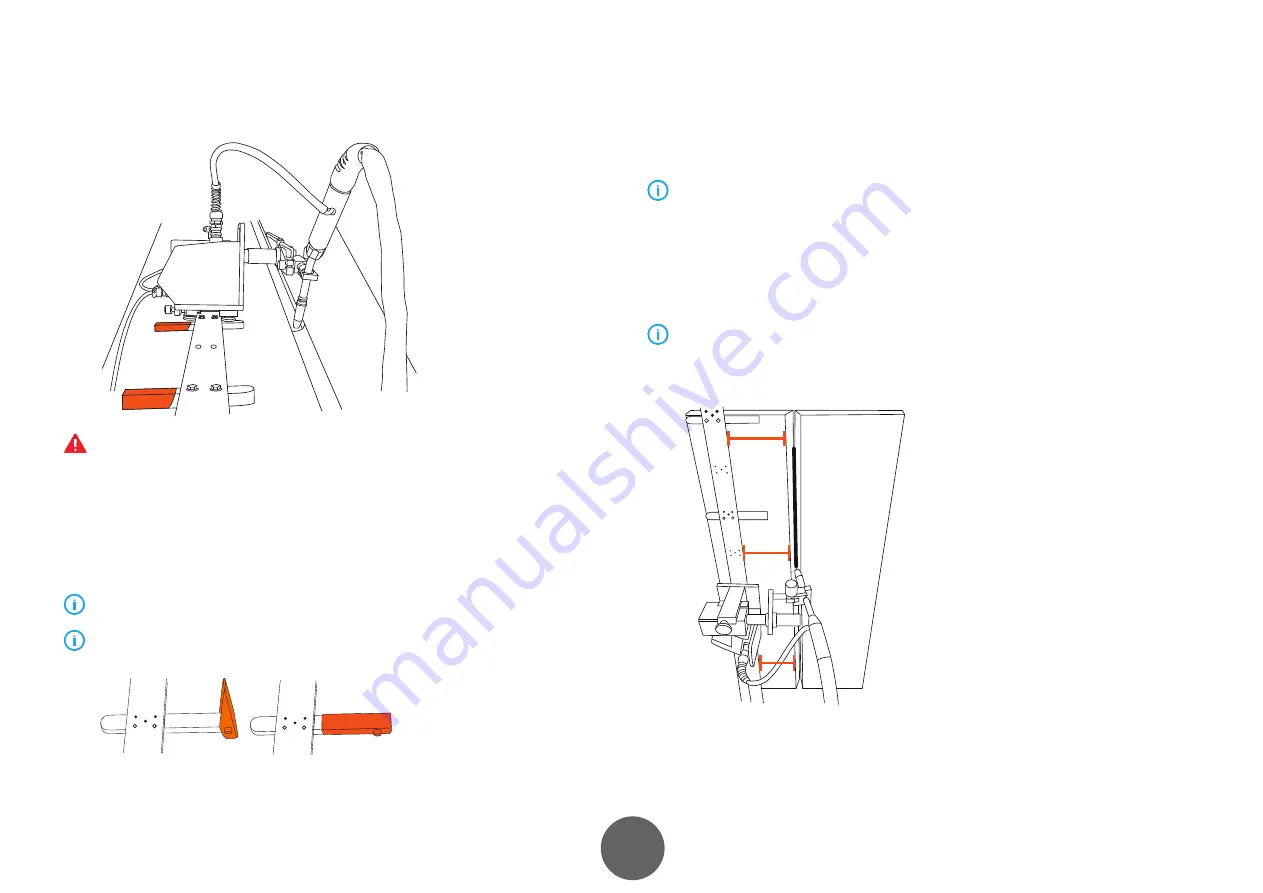
2.3 Installing the rail
The rail contains powerful neodymium magnets that may cause injuries. Always use
a stopper at the last end of the rail or sequence of rails to avoid dropping the carriage.
Dropping the carriage may break it or cause an injury.
Fasten the fixing brackets to the aluminum rail:
• Use two M8 bolts.
• Use either magnetic brackets or suction brackets.
• Quick clamping mechanism.
For safety reasons, use 8 magnets per 2.5 m of aluminum rail.
One magnetic attachment kit contains 8 magnets that serve a rail of 2.5 meters.
Released
Clamped
2.4 Adjusting the rail
1. Place the rail parallel to the joint at about 200 mm distance from it.
2. Fine adjust with a plastic hammer.
You can adjust distance by aligning the displacement of the carriage. Use standard
distance between the rail and the weld in order to minimize the need for adjustment
during welding.
The more accurate the alignment, the less adjustment is needed during welding. When
welding, PC position rail should be mounted above the groove. The rail bends around
items with minimum outer diameter of about 1.5 m.
If the diameter is smaller than 2500 mm, the rail must be rolled to shape. If the
diameter is more than 2500 mm, a straight rail can be used and magnets can make the
bending.
200 m
200 m
200 m
Summary of Contents for A5 MIG Rail System 2500
Page 1: ...2500 1920350 R01 A5 MIG Rail System EN OPERATING MANUAL...
Page 18: ......


