3
Installation Instructions Kemlan Natural Draft Electronic Ignition Gas Fireplaces
Before Installation
The Natural Draft Electronic Ignition (N.D.E.I.) flue
system shall be installed by authorized personnel in
accordance with the manufacturer’s installation
instructions, local gas fitting regulations, municipal
building codes, electrical wiring regulations, and any
other statutory regulations. Contact your local building
authorities about restrictions and installation inspections
that may be required. If in doubt contact your local
dealer or Kemlan’s Head office.
IMPORTANT AUSTRALIAN CODES:
•
Australian Standards AS 5601 Gas Installation
•
Australian Standards AS 3000 Electrical
Important Safety Notes
•
Comply with all instructions in manual including
clearances to combustible material.
•
Do not operate without fully assembling all
components.
•
All open gas fires require ventilation in the room.
•
Do not connect to any other air distribution duct or
system.
•
An A.G.A approved cowl is required at flue terminal.
•
Air movement of systems- A decorative gas log fire
must not be installed where the operation of any
ventilation system, fan or air blower could in any
circumstances cause the air pressure to be less than
atmospheric at the appliance.
•
Do not block or restrict chimney.
•
After installing appliance check that the flue draws
well with smoke pellet.
•
Kemlan recommends that all gas fires be serviced
every year.
•
All gas units must be fitted by a licensed gas fitter.
•
It is the responsibility of the gas fitter to follow the
regulations set out in the Gas Code that dictate the
procedures to follow when installing a gas appliance,
particularly regarding gas pipe sizing and checking of
pressures.
Installation
1
The N.D.E.I. system is supplied with all
required electrical fittings. Work needs to be
undertaken by a licensed electrician if extending
wiring. Wiring requires clearance of minimum
100mm to flues and fireplace body due to heat. See
Wiring diagram page 15. Wiring must be positively
secured away from heat source.
2
An isolation switch needs to be provided if
connecting within fireplace framework.
3
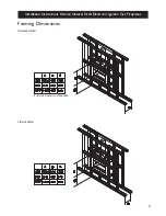
Build frame to specifications provided. Note: 80mm
clearance above fireplace and 5mm to front surface
of firebox.
4
Unit located on 10mm fiber cement sheeting.
Sheeting requires 5 x 50mm holes drilled for air
access to gas burner.
5
Unit and flues to be installed prior to plastering.
6
Gas line run to desired position prior to plastering.
7
A minimum height of 150mm from floor needs to be
available for use of front fascia on firebox.
8
Clearance of 50mm to vertical flue.
9
Allow for a minimum flue height of 3.6m.
10 All flue components to be riveted together.
11 Ventilation is required under fireplace to allow for
sufficient air to gas burner. (Note Elevation drawing)
12 Rooms with Gas Open Fires require fresh air vents
of 400sq centimetres for each Decorative Gas, Coal
Fire.

