


ELECTRICAL VOLTAGE: Ensure that
1.
The power supply is isolated before any installation or maintenance work is carried out.
2.
The voltage, working fluid and the maximum working pressure stated on the product nameplate is suitable for the working
environment.
3.
All work must be carried out by a qualified electrical engineer in accordance with all local and national electrical codes.
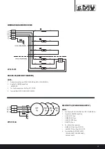
ELECTRICAL INSTALLATION
TERMINAL BOX
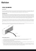
Each unit is fitted with a terminal box (es), fitted on the right hand side when looking at the air discharge. Refrigeration connections are at the opposite end to
terminal box. Access to terminal box is via the unit end cover secured with four screws.
All field wiring should be Copper and correctly sizes for the name plate current. Cable entry should be via knockouts provided and protected with a bush or
grommet.
Unit electrical schematic is secured to the inside of the terminal box or end cover.
MOTORS
All motors are EC (electronically commutated) and wired to the terminal box. Wires are fixed to a screw or ‘cage clamp’ terminal strip.
DEFROST HEATERS
Defrost heaters, when fitted, are stainless steel outer sheath terminated with a sealed black cable at the cold end. Depending on the model defrost heater will
the straight (linked pair) or ‘U’ shape. Heater are either secured to the inner drain tray or mounted in the evaporator coil and locked with a spring or retaining
clamp to prevent heater creep.
Heater withdrawal is via the connection end and requires a minimum 609mm clearance on KEC and 1219mm on UKME.
CLEANING - DANGER
Water or foam spray should not be directly sprayed at the motors or terminal box. Moisture ingress can result in failure or electrical short circuit.
CONTROL BOX
Remote control boxes (not supplied) should be located outside the cold room. Connecting wire should be adequately protected and sealed to prevent moisture
ingress.


