14
JS PRESSURE RELIEF VALVES
© 2017 Kelso Technologies (USA) Inc. All Kelso Valves are Patent Protected. Detailed designs are subject to change without notice.
Kelso Technologies Inc. 1526 Texas Ave, Bonham, TX. 75418, Phone: (903) 583-9200
Document No. - KTUD112
Revision 6
–
2/7/2022 (Original Release 12/7/2015)
www.kelsotech.com
Printed in U.S.A.
If any component of the bearing assembly is damaged, the assembly should be
replaced. Note: Not all models contain a bearing assembly.
3.
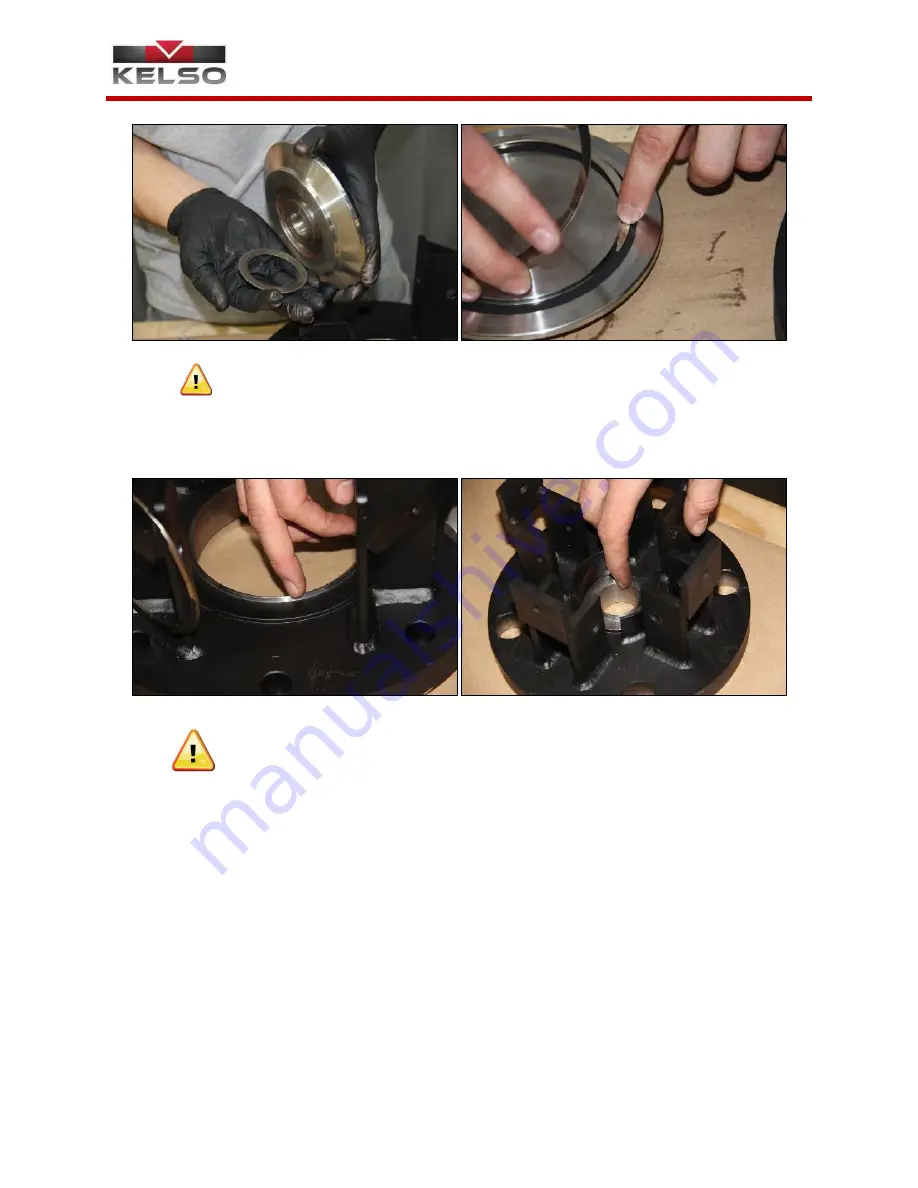
The valve seat, or the crown of the seat, must be free from radial cuts, rust, and
corrosion
(Figure 4.7 & 4.8)
. The valve seat is most crucial for correct valve
operation and any discontinuity can cause the valve to leak.
Repair work on pressure devices that involves machining, grinding, welding or
other alterations/modifications can be performed only by the valve
manufacturer, car owner, or a
user with the valve manufacturer’s permissions.
(AAR M-1002 Appendix A, Paragraph 3.11)
4.
The adjustment screw should be removed from the spring block in order to
examine the threads. A visual exam is all that is needed for the adjustment
screw, unless irregularities exist. Some dings and wear are allowed as long as
the parallel wrenching surfaces, or the hex head, at the top of the screw remain
square and the threads are not damaged. If the surfaces become rounded, the
adjustment screw must be replaced. The threads of the screw should be clean
and lightly lubricated
(Figure 4.9, 4.10, 4.11 & 4.12)
. An appropriately sized
thread die can be used to correct small imperfections. If cracks and/or
fractures are discovered, the adjustment screw should be replaced. The nut
shown in
Figure 4.11
should not be removed. This nut acts as a stop for the
sealing disc and is held in place by a roll pin. Verify that the roll pin is present
and securely in place (if applicable).
Figure 4.5
Figure 4.6
Figure 4.8
Figure 4.7


