background image

27

Table of contents

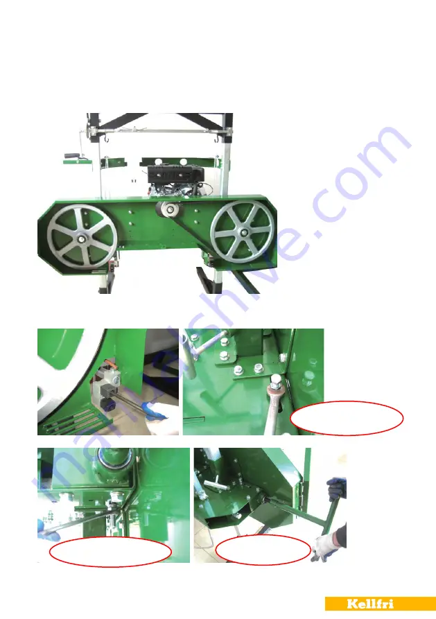
INSTALLATION AND ADJUSTMENT OF SAW BLADE

Instructions below must never be performed when the engine is running. For safety, remove 

the spark plug cap. Gloves and eye protection is recommended to use when working with the 

band saw.

1.) Loosen the 3 bolts with the 13 mm wrench and remove the protective cover.

2.) Loosen hex screw (# 91) on the blade guide blocks (# 90) on both the left and right side. 

Loosen the upper and lower mounting bolts and release the clamping bolt (# 1). Move the 

adjustment bolt forward for easier mounting of band saw. 


mounting bolt- top

mounting bolt - bottom

Tighten bolt

1

2

3

4

Summary of Contents for 21-SV500B

Page 1: ...Read this manual carefully before using the product Translated from the original 21 SV500B SAWMILL...

Page 2: ...6 Personal Protection 7 Surroundings 7 Before use 8 Installation instructions sawmill 9 21 Use 22 Starting the engine 22 Secure the log on the rail 22 Sawing 22 After use 23 Transport and storing 23...

Page 3: ...with belt guides bear ings service friendly and with a protected design Powerful engine with power transmission through the belt By putting the rails in absolute scale you will have a band saw with h...

Page 4: ...nd regulations and the rules of the Animal Welfare Act Persons under 15 years old and people with mental illness may not use these product DANGER Careful NB Warning symbols identify important safety a...

Page 5: ...is re used Do not change the engine settings unless it is told by the engine manufacturer Install the machine on a flat surface People with pacemakers should consult their doctor before using the mach...

Page 6: ...rayed or otherwise unreadable order new decals SYMBOL EXPLANATION Readthemanual Stoptheengineforrepairs Warning Ejection of objects Dangerzone WARNING Rotatingparts blade WARNING ProhibitiontoStayonth...

Page 7: ...rotective mask while driving SURROUNDINGS Make sure your working area is clear from people children and objects before installing and using the machine Risk of serious injuries can occur during operat...

Page 8: ...roduct knowledge is achieved The user customer is responsible to handle the situation correctly The product should not be taken into use unless it can be done in a safe way for the user Warning For sa...

Page 9: ...ILL 1 Remove all packaging material place the main unit standing see picture below on a flat surface 2 Fit 2 square sections 30 in the fixing pipes on the main unit left and right Loosen the locking h...

Page 10: ...10 Table of contents 3 Take out all parts for the carriage for a list of all parts See Figure I II III Loosen the bolts with 16 mm wrench then mount the feet on the square profile 30 30 30...

Page 11: ...5 Assemble 50 cranking bar 65 the nut is tightened with a 19 mm wrench Fit the han dle tighten the nuts using 2x 13mm wrenches see pictures below Fit the bar on the stabi liser bar check that the cran...

Page 12: ...12 Table of contents...

Page 13: ...13 Table of contents 6 Mount the pawl 57 as shown below and mount the tension spring 57 1 2 3 4...

Page 14: ...right hook of stabiliser and the short on the left left hook position of right and left is determined when the operator is standing in front of the machine Fit the wire loop on the hook the wire is t...

Page 15: ...sh up the latch and turn it forward or backward to raise or lower the carriage 10 Adjust the carriage to make it straight Crank up the carriage until the wires are tightened Use a leveler to check whi...

Page 16: ...me 101 on the square profile loosen the fixing bolts with 13mm span ner and fit the frame Then mount attachment for the water tank and bracket for the throttle control 105 see pictures below Bolts are...

Page 17: ...Loosen the bolts 40 on the lower part of the main unit with 16mm wrench as shown in the pictures below and mount the copper pipe 92 located in the end of the water hose on the right side Adjust the c...

Page 18: ...s standard delivery The sections are aligned and bolted together into a track for the carriage Fit 5 trans verse log support but do not tighten the bolts yet see picture below b Assemble the log clamp...

Page 19: ...contents d Install the timber support 138 139 Use the appropriate support long guides are suit able for large logs and short guides are suitable for smaller logs e Lubricate the thread and fit the lo...

Page 20: ...adjustable feet g Install the mounting plate on the outside of the track do not tighten the bolts yet h Lift the saw carriage on the rails Warning saw carriage weighs a lot were extreme caution when...

Page 21: ...rails push the saw carriage ahead to see if it runs smoothly on the rails adjust the height of the support feet if needed otherwise tighten all bolts Check rail joint it is important that both section...

Page 22: ...6 After a few minutes of warming up at idle adjust the throttle to the factory setting for the work to give the engine a normal working speed of up to 3600 RPM Warning If the throttle is changed to i...

Page 23: ...only original replacement parts or spare parts with equivalent performance to reduce the risk of damage All repairs and connec tions with electricity must be performed by a qualified person Always fol...

Page 24: ...and the crankshaft with oil before each use Lubricate the tension handles with grease once a month Before storing the machine it might be good to perform service to ensure that the machine works as i...

Page 25: ...blade jumps off the band wheel 1 The saw blade tension is insufficient 2 Improper adjustment of the saw band guide 3 The belts are worn 4 The band saw blade is dull 5 Feed speed is too fast 1 Adjust t...

Page 26: ...ate 3 The log is loose 4 Teeth are filled with chips dirt 1 Replace band saw blade 2 Remove the belt the teeth must be facing the rails The mill vibrates too much 1 The log does not sit firmly on the...

Page 27: ...mmended to use when working with the band saw 1 Loosen the 3 bolts with the 13 mm wrench and remove the protective cover 2 Loosen hex screw 91 on the blade guide blocks 90 on both the left and right s...

Page 28: ...ls the lower part of the blade should mounted between the 2 band guides 90 tighten the blade 4 Please note It is important that the bolt 11 is in the center of the band wheel shaft 9 in order to make...

Page 29: ...TURE 1 Loosen the adjustment bolt 11 tighten the bolt 1 until Tension band wheel is straight If the band wheel is skewed according PICTURE 2 the adjustment of the bolt should be tightened clockwise an...

Page 30: ...st it up until you have the correct height If the band wheel is skewed as shown in PICTURE 4 the bolt is adjusted downwards It is important that the upper and bottom nuts are adjusted simultaneously B...

Page 31: ...this affects the blade s function Adjust the blade so that it runs smoothly adjust if necessary then tighten bolts The distance between the band and the up per and bottom side of the blocks should be...

Page 32: ...32 Table of contents BLUEPRINT I CARRIAGE...

Page 33: ...33 Table of contents BLUEPRINT II SQUARE PROFILE BLUEPRINT III THE CARRIAGE FEET...

Page 34: ...34 Table of contents BLUEPRINT V BAND WHEELS BLUEPRINT VI RAILS...

Page 35: ...haft 2 13 Spring washer 16 2 87 Bolt M10x12 2 14 Flat bar 2 88 Bracket 2 15 Angle bracket 2 89 Bearings 6200 2 16 Washers 10 106 90 Band Blocks 4 17 Bolt M10x25 48 91 Bolt M8x40 4 18 Fixing tube 2 92...

Page 36: ...45 Lock nut M6 10 119 Bolt M8x20 11 46 Fixing plate 1 120 V belt B 1422 1 47 Cable Locking 2 121 V belt B1981 1 48 Wire 2 122 Washer 10 t4 2 49 Bolt M12x55 1 123 Locking ring 62 2 50 Crankshaft 1 124...

Page 37: ...r M8 4 140 Iron Plate splicing 2 67 Lock nut M8 20 141 Stabilisation Profile splic ing 1 68 Attachment 1 142 Nail 1 69 Engine 1 143 Pin 1 70 Bolt M10x50 6 144 Iron Profile 1 71 Washers 8 145 Stabilisa...

Page 38: ...n the pictures below Extension rails mounted in the center Remove the existing cross bar picture 1 and then install the extension rails and an additional cross bar that comes with the rails picture 2...

Page 39: ...er number Adress Invoice number E mail Phone no Signiture Date When was the product delivered When was the product taken into operation Did the product functioned as it should upon the first operation...

Page 40: ...ntee do not cover Labour costs Travel expenses Any modification that the buyer himself has had made Any consequential damages that occurred due to damage to the machine Damage due to normal deteriorat...

Reviews: