background image

3.2 Forseeable misuse

In principle, any operation that could impair the safety of the system must be
avoided and is considered an impermissible use. This includes, among others:

– Extraction of substances for which the system was not designed to.

– Disassembly and operation without the factory fitted intake or exhaust grids.

– Throwing objects through the mounted intake or exhaust grilles.

– Placing objects on the exhaust air grid.

– No collection of cigarette butts or other burning objects.

– No application as vacuum cleaner or the capture of waste during cleaning work

for example.

– Unauthorized modifaction or retrofitting of the system by operator or by third

parties authorized by him.

System may further not be applied and used for following conditions:

Installation site:

Outdoor installation is not permitted.

Separation of fumes and gases:

Separation of fumes and gases is not
possible

Improper temperature at the installation
site:

Shortfall of the minimum temperature of
- 20 °C. Exceedance of the maximum
temperature of + 60 °C.

Impermissible ex-zones:

System may not be placed and operated
in an ex-zone.

The list of inadmissible use does not claim to be complete. The separator may only
be used under the conditions specified in the chapter "Intended Use".

Any other usage of the system is seen as improper usage. Keller Lufttechnik
GmbH + Co. KG is not liable for possible damage to persons or material resulting
from improper usage.

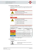
NOTICE

Hazard by improper usage or operation!

Persons may be injured or system be damaged.

a)

Please contact Keller Lufttechnik GmbH + Co. KG in case of
any insecurities concerning the system application.

b)

Do not operate the system on the basis of assumptions.

Operating Manual AmbiCube

Safety

Page 13 of 40

Version: 2 | en
Subject to technical changes

Summary of Contents for AmbiCube

Page 1: ...Original operating manual Operating Manual Room air extraction unit AmbiCube Version 2 Release Date 14 12 2020 ...

Page 2: ...l is designed for installation operating monitoring and servicing staff It contains regu lations and directives as well as drawings of a technical nature All information included in this manual should be handled as strictly confidential It must not be used for competitive purposes and may not be copied in full or in part or be made available or handed over to third parties Page 2 of 40 Version 2 e...

Page 3: ...0 7 3 Switching off the room air cleaner 20 7 4 Set the room air cleaner safely out of operation 21 8 Setting values 22 8 1 Example for setting the potentiometer 22 9 Troubleshooting 25 9 1 Fan does not start 25 9 2 Maximum filter resistance exceeded 25 9 3 Unusual running noises 25 10 Maintenance 27 10 1 Maintenance table 27 10 2 Check setting value 27 10 3 Check air outlet 28 10 4 Remove objects...

Page 4: ...Operating Manual AmbiCube Contents Page 4 of 40 Version 2 en Subject to technical changes ...

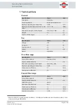
Page 5: ...air filter Number of filter elements 1 pcs Filter class according to ISO 16890 ISO ePM1min 65 Maximum operating air volume flow 1 600 m h Initial pressure difference 1 1 mbar Final pressure difference 4 5 mbar Second filter stage Specification Value Unit Type of filter element HEPA filter Number of filter elements 1 pcs HEPA filter group HEPA Filter class after EN 1822 H14 Initial pressure differe...

Page 6: ...ication Value Unit Separation efficiency integral value 2 99 995 Each HEPA filter is subject to individual testing in accordance with EN 1822 The original test certificate is enclosed with each HEPA filter 2 The indicated values refer to MPPS most penetrating particle size minimum separation efficiency ...

Page 7: ...ted activities has read and understood the operating instructions All activities must only be carried out in accordance with the instructions in this op erating manual and not on the basis of assumptions In case of doubt or if you re quire further information please contact Keller Lufttechnik GmbH Co KG 2 2 Qualification of the personnel Work and activities on the product may only be performed by ...

Page 8: ...ed rules of technology for example VDE guidelines DIN standards Qualified personnel must be able to assess the work assigned to them recognize possible dangers and avoid them Qualified personnel must be authorized by the person responsible for the safety of the system to perform the required work and activities If the qualified personnel has been trained by the manufacturer to per form safety crit...

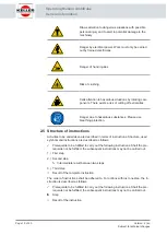
Page 9: ...he color shades depend on potential consequences in case of disregard The following chart shows shades and meaning of signal words as well as the color display Signal word Meaning Consequences in case of disregard DANGER Immediate hazard with high risk Death or heavy injuries WARNING Potential hazardous situation Death or heavy injuries CAUTION Potential hazardous situation Minor injuries possible...

Page 10: ...instructions Activities to be undertaken are described in terms of instructions Structure used symbols and instructions are described as follows ü Prerequisite to be fulfilled to carry out the following instructions Shall the pre requisite not be fulfilled the subsequent instructions may not be carried out 1 First step 2 Second step Ä Intermediate result between two steps 3 Third step ð Result of ...

Page 11: ...storage before installation and initial start up Knowledge and implementation of the information in the operating manual Repair only by authorized personnel Correct operation Operation with the intended intact protective devices or systems Operation without change in design Compliance with maintenance and inspection intervals Exclusive use of original spare parts from the manufacturer Notification...

Page 12: ... of ignition sources is not permitted Permissible ex zones Installation of the separator may not happen in an ex zone Temperature at place of installation The minimum temperature 5 C may not be fallen below The maximum tem perature 40 C may not be exceeded Typical applications are the cleaning of indoor air in classrooms medical practices restaurants and public buildings Included in the intended u...

Page 13: ...ation is not permitted Separation of fumes and gases Separation of fumes and gases is not possible Improper temperature at the installation site Shortfall of the minimum temperature of 20 C Exceedance of the maximum temperature of 60 C Impermissible ex zones System may not be placed and operated in an ex zone The list of inadmissible use does not claim to be complete The separator may only be used...

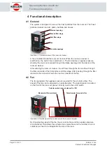
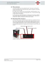
Page 14: ...eaner After entering the room air cleaner the air flows through the fan and then through the filter elements of the first and second filter stage After passing through the filter elements the cleaned air exits the room air cleaner at the top 4 2 Fan The fan generates the negative pressure required for the air volume flow The speed of the fan can be adjusted by a potentiometer The potentiometer is ...

Page 15: ...sible filter resistance final pressure difference is reached 4 4 Manometer filter resistance The fine surface structure of the filter elements represents a resistance for the air flow This so called filter resistance is determined by a differential pressure meas urement measuring the pressure before and after the filter elements In the air cleaner the differential pressure is commonly measured for...

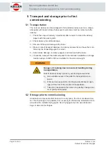
Page 16: ...livery papers and document with photos 6 If possible transport the delivered pallet to the intended installation or storage location using a forklift or lift truck suitable for the size and weight WARNING Danger of crushing due to incorrect handling during transportation Risk of death or heavy injuries by overturning components a Use available recess of the pallet for transportation pur poses b En...

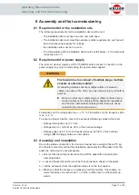
Page 17: ...he characteristic values printed there are not ex ceeded by the connected devices Fluctuations on the voltage side max 10 Fluctuations on the frequency side max 2 To ensure a proper function may not be exceeded following values at the feed Voltage interruptions up to 10 ms Voltage drop to 1 term Max 20 of the nominal voltage Voltage peaks up to 1 5 ms with peak values up to 200 of the nominal volt...

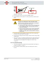
Page 18: ... the cable is not wet or damp Especially after transport in cold outside temperatures and subsequent in stallation in the room there is a risk of moisture on the con nection cable 7 Connect the flat end of the supplied connection cable to the corresponding connector on the rear of the room air cleaner 8 Connect the round plug of the power supply connection cable to the grounding contact socket ð T...

Page 19: ...ront of the room air cleaner The displayed value must be clearly below 8 5 mbar If the value is above 8 5 mbar or only slightly below this value the cause must be determ ined See Chapter Maximum filter resistance exceeded Page 25 7 If the value does not deviate the room air cleaner can be adjusted to the de sired target value using the potentiometer on the front The setpoint value de pends on vari...

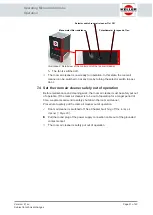
Page 20: ...ady to operate condition 1 Make sure that there are no objects in front of the air intake openings 2 Make sure that there are no objects on the air outlet opening 3 Turn the selector switch on the front of the room air cleaner to position I Selector switch room air cleaner On Off Manometer filter resistance Potentiometer for speed of fan Illustration 7 Detail view of the control unit of the room a...

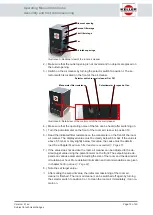
Page 21: ...e maintenance and cleaning work the room air cleaner must be safely put out of operation If the room air cleaner is to be out of operation for a longer period of time we also recommend to safely shut down the room air cleaner Procedure to safely put the room air cleaner out of operation ü Room air cleaner is switched off See Chapter Switching off the room air cleaner Page 20 u Pull the round plug ...

Page 22: ...by due to increasing loading of the filter elements the filter resistance increases and the volume flow decreases accordingly Filter resistant mbar Air volume flow m h Differential pressure max Settings on the controller Characteristic curve of the unit in new condition Illustration 9 Characteristic curves of the unit The data for the settings are updated continuously The current settings can be f...

Page 23: ...curve You can leave this state until you reach the minimum flow rate you can read this point on the manometer In our example this point is at 3 4mbar Filter resistant mbar Air volume flow m h Differential pressure max Settings on the controller Characteristic curve of the unit in new condition Recommended air volume flow Air flow volume min 3 4 mbar Start End Illustration 11 Reaching the minimum a...

Page 24: ...ow volume min 5 4 mbar End new Start new Illustration 12 New setting of the potentiometer You can keep this state until you reach the minimum flow rate You can read this point on the manometer in our example at 5 4mbar You can repeat this procedure until you either reach position 10 on the controller or the manometer shows 8 5mbar At this point the filter stages should be replaced This procedure e...

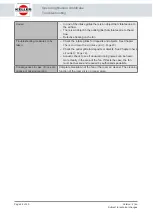
Page 25: ...tomer s power supply Have the fan or the internal power supply checked by an author ized electrician and have it repaired if necessary Consequences in case of non com pliance or missing reaction The room air cleaner cannot be switched on The cleaning function of the room air is no longer given 9 2 Maximum filter resistance exceeded Description A value of 8 5 mbar is permanently exceeded on the man...

Page 26: ...he intake grilles for deposits and objects See Chapter Check and clean the air intake grid Page 29 Check the outlet grille for deposits or objects See Chapter Check air outlet Page 28 Acoustic check to see if unusual running noises can be heard more clearly in the area of the fan If this is the case the fan must be checked and repaired by authorized specialists Consequences in case of non com plia...

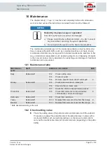
Page 27: ...nance cycle Staff Additional information SAB Daily Skilled staff 10 2 Check setting value 10 3 Check air outlet 10 4 Remove objects below the air outlet grid X Weekly Skilled staff 10 5 Check and clean the air intake grid 10 6 Cleaning the air intake area 10 7 Check the unit for unusual running noises Trimestrial Skilled staff 10 9 Check filter elements for impermissible contamination odors and da...

Page 28: ...cluding magazines or similar are placed on the grille of the air outlet If necessary re move these objects Blow out opening Second filter stage First filter stage Fan Air intake openings Illustration 14 Sectional view of the room air cleaner 2 Make sure that no objects have been put into the grid that could clog or block the grid 3 Visual inspection of the area below the grid If objects are visibl...

Page 29: ...sible con tamination odors and damage Page 31 7 Place the air outlet grid back on the room air cleaner and screw it on tightly with the four fastening screws 8 Connect the round plug of the power supply connection cable to the grounding contact socket ð The room air cleaner is now ready for operation In this state the room air cleaner can be switched on at any time by turning the selector switch t...

Page 30: ...r intake area Page 30 10 6 Cleaning the air intake area Procedure for cleaning the suction area 1 Turn the selector switch on the front of the room air cleaner to position 0 Ä The fan is switched off 2 Pull the round plug of the power supply connection cable out of the grounded contact socket 3 Loosen and remove the 4 Phillips screws at one of the intake grids Fastening screws Illustration 18 Fixi...

Page 31: ...contamination odors and damage WARNING Health hazard due to lack of protective equipment Damage to health by inhalation of whirled up dust or by contact with the separated substances u Wear suitable protective equipment at least a breathing mask and gloves The filter elements clog up with the extracted particles and aerosols during opera tion and must be checked regularly for impermissible contami...

Page 32: ... to a well ventilated area The room where the fil ter elements are changed should be well ventilated and should not be entered by any other persons without appropriate protective equipment during and im mediately after the change of the filter elements until the room air is changed or cleaned 4 Loosen and remove the four fastening screws on the top of the air outlet grid A 4 mm Allen wrench is req...

Page 33: ... element of the first filter stage 16 Replace the mounting bracket on the two threaded rods The open end must point towards the second filter stage 17 Screw the two wing nuts onto the threaded rods and tighten them firmly By tightening the fixing bracket is pressed onto the filter element of the second fil ter stage which tightens the filter elements 18 Place the air outlet grid back on the room a...

Page 34: ... be extrac ted shall be worn a suitable safety equipment b Safety gloves shall be worn especially for the disassambly of edgy and sharp components c Secure components against turning over or falling down d Secure components against turning over or falling down Prior to starting the disassembly 1 Save system shutdown 2 Disconnect system from power supply 3 Disconnect system from compressed air net ...

Page 35: ...al components shall be supplied to scrap metal Control and electronical com ponents shall be supplied to electronic waste National and local regulations for waste disposal shall be adhered to when disposing electrical devices Remaining components shall be disposed separated according to their material characterist ics Detailed information can be obtained from the responsible authority Operating Ma...

Page 36: ...out opening Second filter stage First filter stage Fan Air intake openings Illustration 23 Sectional view of the room air cleaner Description Quantity Unit Article number Spare parts type Filter element first filter stage 1 pcs 8000402375 Wearing part Filter element second filter stage 1 pcs 8000402379 Wearing part ...

Page 37: ...14 Attachment 14 1 Characteristic curve diagram Operating Manual AmbiCube Attachment Page 37 of 40 Version 2 en Subject to technical changes ...

Page 38: ...Operating Manual AmbiCube Attachment Page 38 of 40 Version 2 en Subject to technical changes ...
Page 39: ...tzer Straße 13 Fon 49 6258 941899 0 Fax 49 6258 941899 5 info lwv gmbh de 73230 Kirchheim unter Teck Keller Lufttechnik GmbH Co KG Thomas Schneider Neue Weilheimer Str 30 Fon 49 7021 574 191 Fax 49 7021 574 130 thomas schneider keller lufttechnik de 89077 Ulm Bernhard Gräter GmbH Seutterweg 9 Fon 49 731 37555 Fax 49 731 33106 bernhard graeter graeter gmbh de 88709 Meersburg UTS Gesellschaft für Um...

Page 40: ...708 Fon 1 8033962000 Fax 1 8033962905 info kellerusa com www kellerusa com China Keller Environmental Equipment Shanghai Co Ltd RM 2001 2002 No 3399 Yuanjiang RD SHANGHAI P C 201109 People s Republic of CHINA Fon 86 2158884408 Fax 86 2158884410 info keller china com www keller china com Keller Lufttechnik GmbH Co KG Neue Weilheimer Straße 30 D 73230 Kirchheim unter Teck Fon 49 0 70 21 5 74 0 info ...

Reviews: