


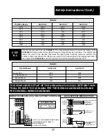


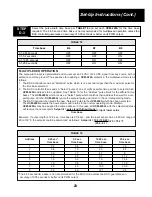


Signal Monitored
Set jumper plugs on
4-20 mA
Positions 1, 7, & 11
1-5 VDC
Positions 2, 7, & 11
26
PWM
INPUT
PWM
INPUT
REM SPT
INPUT
LOC SPT
POT +
LOC SPT
INPUT
LOC SPT
POT –
COMMON
MA SIG
OUTPUT
1
2
3
4
5
6
7
8
9
10
11
12
B3
0
0
0
0
1
1
1
1
B6
0
0
0
0
1
B7
0
0
1
1
X
B8
0
1
0
1
X
B4
0
0
1
1
0
0
1
1
B5
0
1
0
1
0
1
0
1
MUX
ADDR
1
2
3
4
5
6
7
8
A6
0
0
0
0
1
1
1
1
A7
0
0
1
1
0
0
1
1
A8
0
1
0
1
0
1
0
1
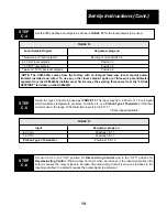
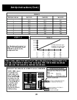
PROP
T.R.
10%
20%
35%
50%
65%
80%
90%
100%
UCM-420A
TIME
BASE
2.65
5.2
12.85
25.6
.59-2.93
A4
0
0
1
1
A5
0
1
0
1
RESET
PER MIN
OFF
0.5
1
2
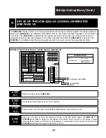
"1" MEANS
TURN SWITCH ON
"0" MEANS
TURN SWITCH OFF
LOCAL
SETPOINT
FEEDBACK
REMOTE
SETPOINT
STATUS
B
A
24 VAC OR 24 VDC POWER
OUTPUT SIGNAL
TO SYSTEM
+
–
+
–
INPUT SIGNAL
MONITORED
–
+
1 2 3 4 5 6 7 8
1 2 3 4 5 6 7 8
FEEDBK
INPUT
24 PWR
SWITCH OFF
SWITCH ON
A3
A2
A1
B1
B2
REVERSE ACTING
BOTH OFF >> REMOTE SETPT
SAMPLE AND HOLD MODE
BOTH OFF >> ANALOG
REMOTE SETPOINT
DIRECT ACTING
LOCAL SETPT ENABLE
REMOTE SETPT ENABLE
PWM REM SETPT SGLE UNIT
PWM REM SETPT MUX MODE
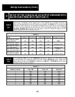
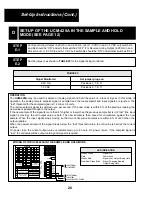
WIRING OF THE UCM-420A IN THE SAMPLE AND HOLD MODE
Steady Green
- Signal O.K.
Dark
- Power Loss
Steady Red
- Signal Lost, Output Being Held
Slow Red/Green Blink - Signal Changing Rapidly.
Output Being Held
LED INDICATION
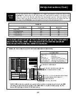
For Direct-Acting Output (4-20 mA in and 4-20 mA out or 1-5 VDC in and 1-5 VDC out) switch A3
and A4 should be “ON” and all other switches ”OFF”. For Reverse Acting Output (4-20 mA in and
20-4 mA out or 1-5 VDC in and 5-1 VDC out) switch A4 should be “ON” and all other switches “OFF.”
STEP
E-1
Set the jumpers as shown in TABLE 23 for the signal being monitored.
STEP
E-2
D
SET-UP OF THE UCM-420A IN THE SAMPLE AND HOLD
MODE (SEE PAGE 12)
TABLE 23
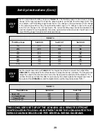
OPERATION
The UCM-420A may be used to sample an analog signal and hold the value on a loss of signal. In this mode of
operation, the analog remote setpoint signal is sampled and the local setpoint and input signals are ignored. The
“lost” threshold for the sampled signal is 3.2 mA or 0.8 volts.
The remote setpoint signal is sampled once per second. If the new value is within 6% of the previous reading, the
new value is passed through to the output.
If the new sample of the signal is more than 6% higher or lower than the previous sample but is not “lost” (the input
signal is moving), the old output value is held. The new sample is then saved for comparison against the next
sample. When the input signal stops moving so that two consecutive samples are within 6% of each other, the
output updates.
When the newest sample of the signal drops below the “lost” threshold value, the old value is held at the current
output.
On power loss, the current output value is remembered up to 6 hours. On power return, if the sampled signal is
“lost,” the old value will be output until a good signal is received.
Set-Up Instructions (Cont.)