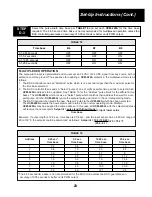
LOC SPT POT +
LOC SPT INPUT
LOC SPT POT –
THREE-WIRE POTENTIOMETER
(5K
W
TO 50 K
W
)
LOCAL SETPOINT
(FACTORY INSTALLED
ON BASIC MODEL)
INCREASE SETPONT
LOC SPT POT +
LOC SPT INPUT
LOC SPT POT –
TWO-WIRE POTENTIOMETER
LOCAL SETPOINT
("XA OPTION ON
PRECON THERMISTOR)
INCREASE
SETPONT
LOC SPT POT +
LOC SPT INPUT
LOC SPT POT –
4-20 MA OR 1-5 VOLT
LOCAL SETPOINT
+
–
COMMON
COMMON
Resets/Minute
Switch A4
Switch A5
Reset OFF
OFF
OFF
0.5 Resets/Minute
OFF
ON
1 Resets/Minute
ON
OFF
2 Resets/Minute
ON
ON
Throttling Range
Switch A6
Switch A7
Switch A8
10%
OFF
OFF
OFF
20%
OFF
OFF
ON
35%
OFF
ON
OFF
50%
OFF
ON
ON
65%
ON
OFF
OFF
80%
ON
OFF
ON
90%
ON
ON
OFF
100%
ON
ON
ON
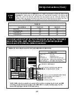
17
PWM
INPUT
PWM
INPUT
REM SPT
INPUT
LOC SPT
POT +
LOC SPT
INPUT
LOC SPT
POT –
FEEDBK
INPUT
24 PWR
COMMON
MA SIG
OUTPUT
1
2
3
4
5
6
7
8
9
10
11
12
LOCAL
SETPOINT
FEEDBACK
REMOTE
SETPOINT
STATUS
B
A
24 VAC OR 24 VDC POWER
4-20 MA, 1-5 VOLT OR THERMISTOR INPUT SIGNAL
4-20 MA SOURCING OUTPUT SIGNAL TO
CONTROLLED DEVICE
+
–
–
+
+
–
SEE
LOCAL
SETPOINT
WIRING
OPTIONS
1 2 3 4 5 6 7 8
1 2 3 4 5 6 7 8
WIRING THE UCM-420A AS A LOCAL SETPOINT CONTROLLER
LOCAL SETPOINT WIRING OPTIONS
Steady Green - Power On
Dark - Power Loss
LED INDICATION
TABLE 8
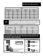
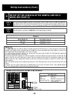
Set the integral reset rate per TABLE 9. The integral reset feature corrects the output of the
UCM-420A to compensate for the offset inherent in proportional-only controllers. The integral reset
ramps the output in the direction that forces the input signal to exactly match the setpoint. The
number of times per minute this offset is overcome by the output signal is the integral reset rate. If
the output of the UCM-420A is used for digital control, set the integral reset rate "OFF."
STEP
B-5
TABLE 9
THIS CONCLUDES SET-UP OF THE UCM-420A AS A LOCAL SETPOINT CON-
TROLLER. WIRE THE UCM-420A PER THE WIRING DIAGRAM BELOW AND
PER GENERAL WIRING DIAGRAMS.
Set-Up Instructions (Cont.)


