


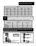


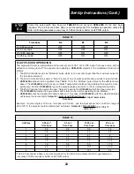


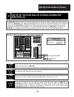


SETTING THROTTLING RANGE
Throttling Range
Switch A6
Switch A7
Switch A8
10%
OFF
OFF
OFF
20%
OFF
OFF
ON
35%
OFF
ON
OFF
50%
OFF
ON
ON
65%
ON
OFF
OFF
80%
ON
OFF
ON
90%
ON
ON
OFF
100%
ON
ON
ON
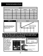
Input
Set jumper plugs on
4-20 mA
Positions 7 & 11
1-5 VDC
Positions 8 & 11
PreCon Type 3 Thermistor
Positions 10 & 12
24
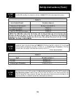
Select the type of input to be used and set jumpers per TABLE 20. The input may be a 4-20 mA or
1-5V signal which measures temperature, pressure, humidity, etc. or a PreCon Type 3 Thermistor.
STEP
D-4
Set switch A3 in the “ON” position for DIrect-Acting Control and in the “OFF” position for
Reverse-Acting Control. (
Direct-Acting Control
is when an increase in the input signal above set-
point causes the output signal to increase.
Reverse-Acting Control
is when an increase in the input
signal above setpoint causes the output signal to decrease.
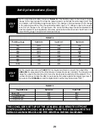
STEP
D-5
Set the proportional throttling range per TABLE 21. The throttling range is the amount of signal
change of the input required to cause the output signal to go through its entire range (4-20 mA).
For example, a 20% throttling range means that a 1 mA change in the input signal causes a 5 mA
change in the output signal. When using the optional thermistor input, a 1°F change in input is the
equivalent of 0.4 mA change in the mA input mode. The correct throttling range cannot be calcu-
lated, but must be adjusted for each application. Generally, systems that respond quickly should
have a narrower throttling range than systems that respond slowly.
STEP
D-6
TABLE 20
TABLE 21
Set-Up Instructions (Cont.)