C-18
I/O Registers
KPCMCIA-12AIAOH User’s Manual
Timer/counter clock source
Bit 2 of the auxiliary control register (base + 15, write) selects the timer/counter clock source. It
is either the internal 1MHz clock (bit 2 is 0) or the external clock (bit 2 is 1). Because of the pin
confinement, the timer/counter external clock input is shared with the A/D external clock input,
which is also the digital input bit 2.
The external clock has a minimum pulse width of more than 100ns and a maximum frequency of
no more than 5MHz, the same as specified in “Clock source.”
Reading the contents of the timer/counter
The content of the up-counter can be read “on the fly” by sending the read latch command. Refer
to “Latch timer/counter command” for more information. Upon receiving the command, the cur-
rent content of the up-counter latches into the read latch register. The timer/counter control logic
guarantees the integrity of the latched value. The read latch operation is independent of the timer/
counter modes. It works in all four modes.
The latched value in the read latch register does not change until next read latch command is
received.
Timer divisor or counter modulus
As described in Section 3, the up-counter always counts up from its initial value (determined by
the reload register) to its final count (always 65535 or hexadecimal FFFF). Suppose D is the
divisor (also called modulus for counter) of the timer and X is the value written into the reload
register. The relation between the two is:
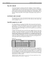
D = 65536 - X
The up-counter will now count up from X to 65535. Avoid D=1 or X=65535 because the up-
counter will be stuck with this value.
Timer/counter overflow
When the timer/counter reaches its final count of 65535, the next rising edge of the selected clock
source reloads the up-counter from the reload register and sets the timer/counter overflow event
latch to 1 (bit 4 of the auxiliary status register, read). This will cause an interrupt if the timer/
counter interrupt is enabled (bit 5 of the auxiliary control register set to 1).
The overflow event latch can be cleared only by writing a 0 into bit 5 of the auxiliary control reg-
ister (originally 1 or 0). Reading the auxiliary status register does not clear the timer/counter over-
flow event latch.
Generally speaking, the timer/counter output will be 1 for one clock cycle time as the timer/
counter overflows (after the cycle when it reaches the final value of 65535). If the timer/counter
is paused or stuck at its final count, the output pin will then be high as long as the final count holds.
The timer/counter is totally independent of the pacer clock, which is dedicated to generating a
sample rate in continuous trigger mode for the A/D converter. It can be used for the D/A converter
to synchronize its channel output updating, as described in “D/A update models.”
Summary of Contents for KPCMCIA-12AIAOH
Page 11: ...1 Introduction...
Page 15: ...2 Installation...
Page 17: ...3 Theory of Operation...
Page 25: ...4 I O Connections...
Page 28: ...5 Optional Accessories...
Page 30: ...A Specifications...
Page 33: ...B PCMCIA Interface...
Page 36: ...C I O Registers...


