


Reviews:
No comments
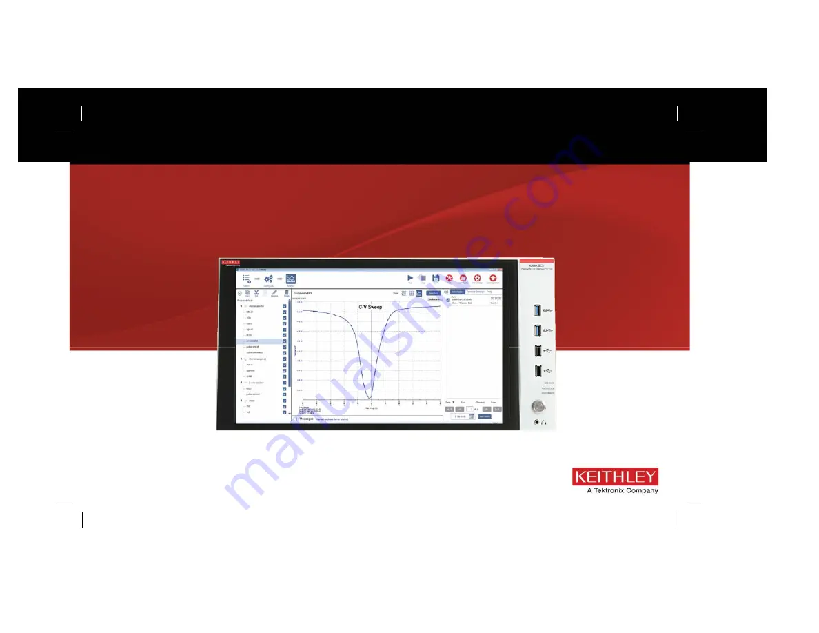
Related manuals for 4200A-SCS-PK3

LevelMaster 7100
Brand: ABB Pages: 2

4690 Series
Brand: ABB Pages: 4

Navigator 550
Brand: ABB Pages: 8

CMG-102
Brand: Utilitech Pages: 2

SACE Emax 2
Brand: ABB Pages: 20

SM1000
Brand: ABB Pages: 8

SM1000
Brand: ABB Pages: 8

Endura AZ20 series
Brand: ABB Pages: 8

Ninja Blade
Brand: Atomos Pages: 4

486
Brand: Keithley Pages: 48

700 Series
Brand: Oakton Pages: 4

2002
Brand: Keithley Pages: 148

2100 Series
Brand: Samson Pages: 4

DS 150
Brand: PAT Pages: 31

DS 150
Brand: PAT Pages: 55

EMU
Brand: rainforest Pages: 2

815
Brand: ECC X-RAY Pages: 14

PRO
Brand: Icare Pages: 3


