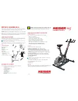
Assembling Bike to Base Frame
Step 1
: Carefully lower the bike onto the base frame over the base screws, with
the front of the bike facing the transport wheels on the Base Frame. (Fig. 1)
Step 2
: Insert one washer on each of the four base frame studs. (Fig. 1)
Step 3
: Install the acorn nuts on the studs and hand tighten. Torque the acorn
nuts with a 16mm or 5/8” crowfoot and torque wrench to 45 Nm (35 ft-lbs) using a
16mm, or 5/8 inch open-end wrench to hold in position. (Fig. 2)
BIKE ASSEMBLY
To calibrate the computer:
The shifter lever must be in the down
position. Holding a pedal, rotate
the crank arm in any direction to
switch the computer on. Once the
computer is on, stop rotating the crank
arm. Move the shifter lever from full
bottom to full top a minimum of five times
(Fig. 12). When you see the computer
display a set of number fives (55:55)
in the time display, the computer is
calibrated.
3
5
6
WARNING!
Failing to install the pedals with
Loctite 242, or crossing the threads will
damage them, and could result in
serious injury to the user.
Mounting Handlebar Assembly
Step 1:
Obtain the handlebar assembly, 6mm Allen wrench, and the socket head
cap screws (M8x1.25 X 12 SS). Observe the location of the two mounting flanges
on the handlebar post. Place the handlebar assembly on the post mounts, aligning
the mounting holes. (Fig. 10)
Step 2
: Tilt the handlebar assembly slightly to place the socket head cap screws
(M8x1.25 X 12 SS) into the mounting holes (Fig. 11). Once each screw has been
started, place the palm of one hand on the center of the handlebar pressing firmly
and evenly onto the handlebar post. With the other hand tighten each screw with
the Allen wrench until the head of each screw just makes contact with each hole.
Now tighten each screw evenly.
11
NOTE
: If installing the M3 computer please do so before mounting the handle-
bars. When the computer installation is complete please return to this step.
Mounting Computer
(Models with computer)
Step 1
: Obtain the #2 Phillips screwdriver and remove the computer mounting
screw from the handlebar tube.
Step 2
: Coil the computer cable into the computer mount cavity (Fig. 8).
Step 3:
Slide the computer up into the two locking ears. Insert and secure the
screw you removed in Step 1 using the #2 Phillips screwdriver (Fig. 9).
10
8
4
Assembling Flywheel, Hub, and Hub Cap
Step 1
: Before starting the assembly of the flywheel, hub, and hub cap, make sure
that the shifter lever is in the downward position. (Fig. 3)
NOTE:
Not following this step may scratch the flywheel.
Step 2
: Remove the plastic wrapping from around the axle, hub, and hub cap.
Remove the hub cap. Obtain the 5 socket head cap screws (M6x1 X 20 SS)
and 5mm Allen wrench. (Fig. 4) Remove the flywheel from its foam envelope.
Assembling Pedal to Crank Arm
Step 1
: Unwrap the pedal set and Loctite 242, obtain the Torque wrench, 15mm
crowfoot, 4” extension, and 15mm open-end wrench.
Step 2
: With a clean cloth, wipe the threaded area of the pedals. Apply
Loctite 242 to the pedal threads. Install the pedals into the crank arms, use
the 15mm open-end wrench to tighten. Finish with the torque wrench, 15mm
crowfoot, and 4” extension. Torque pedals to 45 Nm (35 ft-lbs) (Fig. 7).
NOTE:
Left pedal is LH threads and right pedal is RH threads.
7
1
2
9
Computer mounting screw
Calibrating the Computer
(Models with computer)
NOTE
: Use the foam envelope to handle the flywheel during assembly.
Step 3
: Carefully slide the flywheel between the two magnets (Fig 4. & Fig. 5) and
onto the hub at the same time. Make sure that the flywheel is flush against the hub
and align the screw holes.
Step 4
: Holding the flywheel in position with one hand, install the hubcap and
align the screw holes. Install the socket head cap screws (M6x1 X 20 SS). Using
the 5mm Allen wrench, tighten the screws in a star pattern until snug (as shown
in Fig. 6).
12
See back page for final check and operation.

