

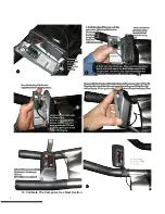
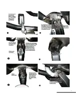

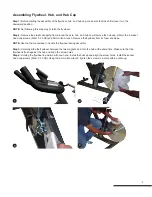


Assembling Flywheel, Hub, and Hub Cap
Step 1:
Before starting the assembly of the flywheel, hub, and hub cap, make sure that the shifter lever is in the
downward position.
NOTE:
Not following this step may scratch the flywheel.
Step 2:
Remove the plastic wrapping from around the axle, hub, and hub cap. Remove the hub cap. Obtain the 5 socket
head cap screws (M6x1 X 20 SS) and 5mm Allen wrench. Remove the flywheel from its foam envelope.
NOTE:
Use the foam envelope to handle the flywheel during assembly.
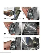
Step 3:
Carefully slide the flywheel between the two magnets and onto the hub at the same time. Make sure that the
flywheel is flush against the hub and align the screw holes.
Step 4:
Holding the flywheel in position with one hand, install the hubcap and align the screw holes. Install the socket
head cap screws (M6x1 X 20 SS). Using the 5mm Allen wrench, tighten the screws in a star pattern until snug.
1
2
3
4
9
Summary of Contents for M3
Page 1: ...M3 User and Service Manual...
Page 6: ...12 Calibrate The Computer See Next Section 4...
Page 7: ...5...
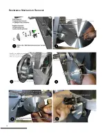
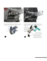
Page 12: ...Resistance Mechanism Removal 10...
Page 13: ...11...
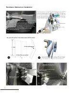
Page 14: ...Resistance Mechanism Installation 12...
Page 15: ...13...
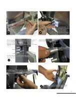
Page 16: ...14...
Page 17: ...Steps For Belt Removal 15...
Page 18: ...Steps for Belt Installation 16...
Page 19: ...Crank Arm and Axle Removal and Installation 17...
Page 20: ...18...
Page 21: ...19...
Page 25: ...23...
Page 26: ...24...
Page 27: ...25...