T-305E User Manual Version 3.5 | 9
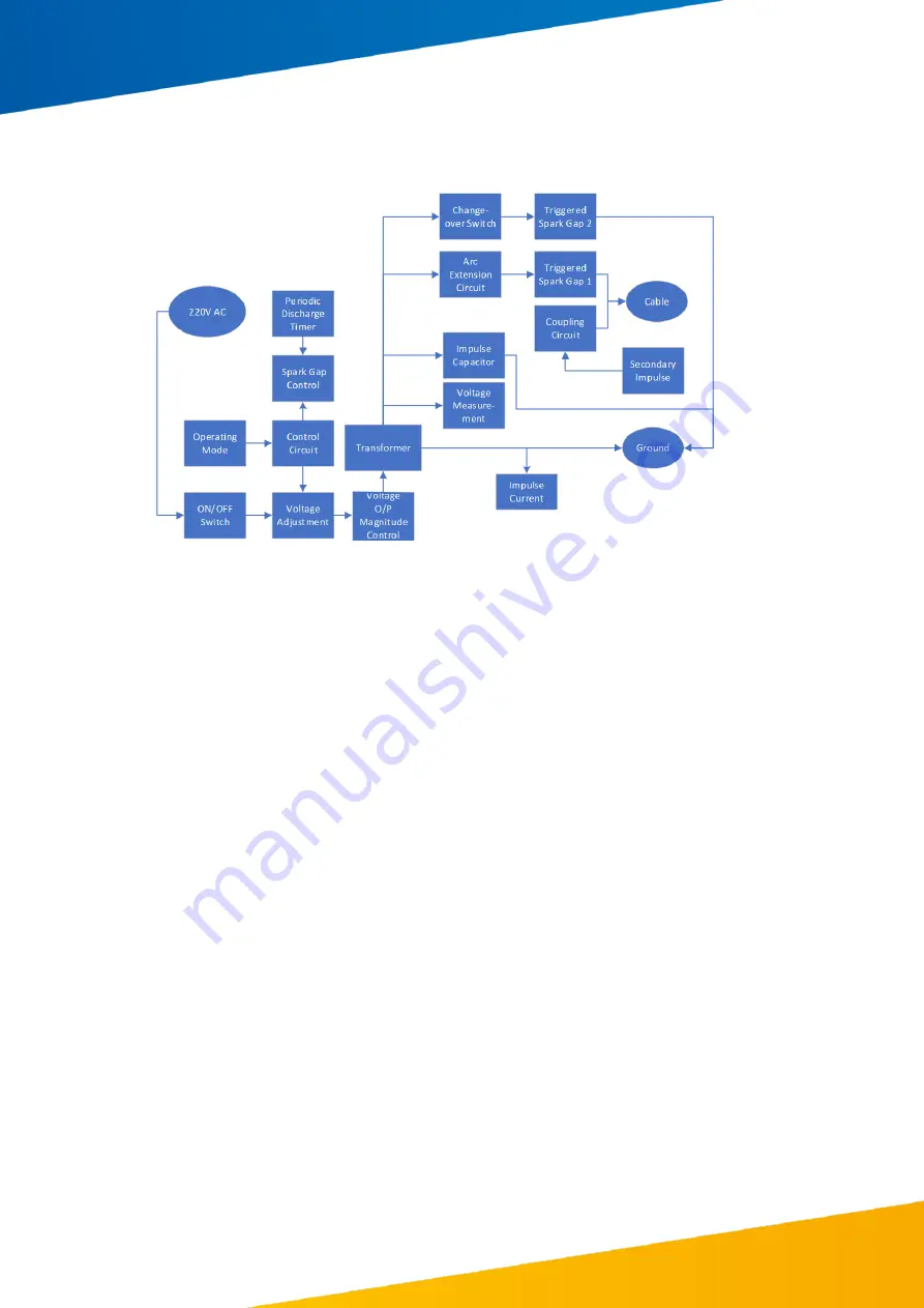
The design of a practical surge generator is more complicated as can be seen in the block
diagram Figure 3.2 for the T-305E.
3.2
DC operation
The surge generator can be used as a DC source by closing switch S1 and applying the
rectified voltage signal directly to the cable. In this way the device may be used to check the
voltage withstand of the cable.
If a fault on the cable breaks down under this voltage, it sets up a travelling wave which
reflects between the fault and the surge generator which can be measured on a suitable
instrument (e.g., The Kehui T-906) through an inductive coupler on the earth lead. The
distance to the fault can be calculated from the time between the voltage peaks on the
resultant waveform and knowledge of the velocity of propagation of the surge.
DC mode can also be used to power a sheath fault locator, such as the Kehui T-H200. Using
the surge generator for this application makes it unnecessary to use a separate power
source such as the Kehui T-100C. Further details can be found in Section 5.
3.3
Surge operation
If the fault cannot be broken down by simply raising the voltage, it will be necessary to send
a surge of energy in to the cable. This is achieved by charging capacitor C to the required
voltage and discharging it into the suspected cable core through switch S1.
The surge of energy in the cable will be reflected from the far end of the cable, such that the
fault is subjected to a voltage approaching twice the value injected (e.g., a surge at 32kV
setting will subject the fault up to 64kV).
The ability to break down the fault is not just a function of the voltage; it is also dependent
on the available energy which is a function of capacitance where the energy in Joules is
equal to ½ CV
2
where C is in µF and V in kV.
Figure 3.2 T-305 Block diagram


